Power supply circuits

a power supply circuit and circuit technology, applied in the direction of power conversion systems, dc-dc conversion, instruments, etc., can solve the problems of low total harmonic distortion (thd) and good line regulation at the same time, complex and difficult design of rcc circuit designs, and poor line regulation. , to achieve the effect of reducing linearity, improving line regulation, and low cos

Active Publication Date: 2018-08-16
SIGNIFY HLDG BV
View PDF1 Cites 6 Cited by
  • Summary
  • Abstract
  • Description
  • Claims
  • Application Information

AI Technical Summary

Benefits of technology

[0010]There is therefore a need for a low cost RCC circuit which avoids the use of an IC control chip and addresses the issues of reduced linearity, namely providing better line regulation. It is also preferable to provide a RCC circuit for driving an LED arrangement which exhibits improved dimming performance.

Problems solved by technology

RCC circuits are, however, not widely used in applications which require high performance.
RCC circuit designs which produce a high power factor, a low total harmonic distortion (THD) and good line regulation at the same time are complex and difficult to design.
RCC circuits which achieve high power factor and low THD performance are known, but such circuits have poor line regulation (in that a varying input voltage significantly affects the output of the driver circuit).
They may also exhibit reduced linearity and inadequate depth of dimming for LED light driving applications.

Method used


Image

  • Power supply circuits
  • Power supply circuits
  • Power supply circuits

Examples


Embodiment Construction

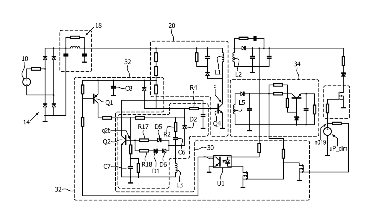
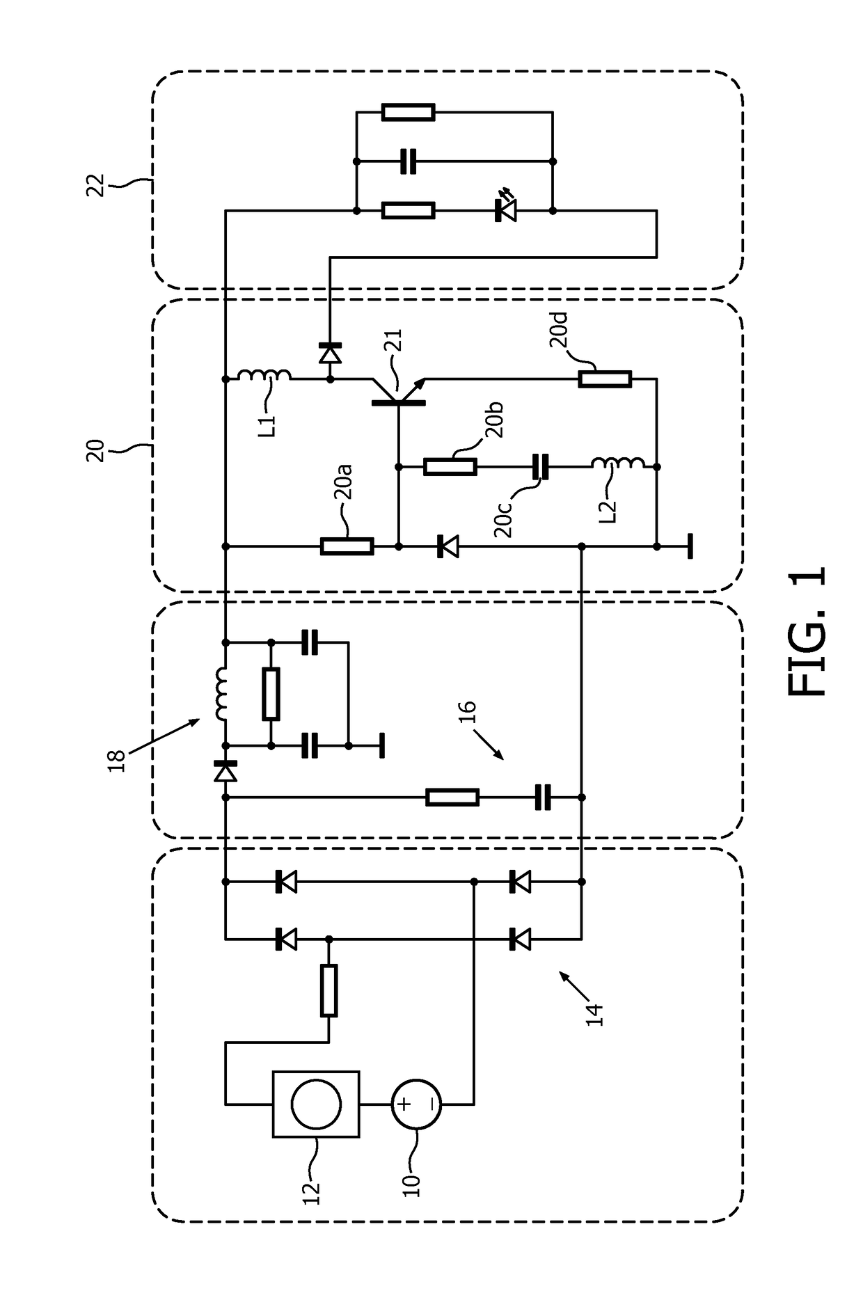
[0043]Proposed is a converter circuit which employs a control circuit for controlling the main switching circuit of the RCC circuit. The control circuit is triggered to operate by an auxiliary inductor which is responsive to a change in voltage at a storage inductor on the primary side of the RCC circuit. An auxiliary inductor is used to trigger the controlling of the main switching circuit, and two charging paths are arranged between the auxiliary inductor and a control capacitor which controls the action of the control circuit.

[0044]Thus, there is proposed a low cost converter circuit which does not use an IC control chip and also exhibits good linearity. The proposed arrangements may also enable the time constant TON of the converter to be flexibly adjusted.

[0045]Embodiments may therefore be used for driving an LED arrangement and achieve a reduction in flickering. Embodiments may also enable deep LED dimming to be achieved. The following embodiment uses RCC (ring choke converter...


PUM


Abstract

Presented is a converter circuit having main switching circuiton a primary side of a transformer, for controlling supply of a current to a storage inductor on the primary side when the main switching circuit is conductive. The convertor circuit comprises: a control circuit operatively coupled to the main switching circuit and for controlling the main switching circuit, the control circuit comprising a control capacitor adapted to enable the control circuit and turn off the main switching circuit; an auxiliary inductor magnetically coupled to the storage inductor and adapted to trigger the control circuit to operate and turn off the main switching circuit in response to a voltage change in the storage inductor when the main switching circuit being conductive; and a charging circuit coupled between the auxiliary inductor and the control capacitor and adapted to enable the auxiliary inductor to charge the control capacitor. The charging circuit comprises first and second charging paths within the primary side between the auxiliary inductor and the control capacitor, the first charging path being conductive and the second charging path being conductive when a voltage across the auxiliary inductor is above a threshold value.

Description

FIELD OF THE INVENTION[0001]This invention relates to power supply circuits, and more particularly switching power supply circuits.BACKGROUND OF THE INVENTION[0002]Switching power supply circuits, including RCC circuits, are widely used as light emitting diode (LED) driver circuits and chargers for electronic devices because of their low cost.[0003]A known RCC driver circuit for an LED light is shown in FIG. 1. This circuit consists of the mains supply, realized e.g. as a 230V mains voltage system 10 with a leading edge dimmer 12. An ordinary diode bridge rectifier 14 is followed by an RC latch 16 to damp high frequency oscillations / ringing. An EMI filter stage 18 supplies the RCC converter 20 with its dc operating supply.[0004]The self-resonating RCC converter works typically in a buck-boost mode making use of two coupled coils L1, L2 to generate a feedback signal controlling the current to be fed to the LED source 22. The inductor L1 acts as an energy store and delivers current to...

Claims


Application Information

Patent Timeline
Patent Type & Authority Applications(United States)
IPC IPC(8): H02M3/335H02M1/36H02M1/00
CPCH02M3/33523H02M1/36H02M3/33553H02M3/33569H02M2001/0006H02M2001/0064H02M1/0006H02M1/0064
Inventor CHEN, ZHI QUAN
Owner SIGNIFY HLDG BV
Why Eureka
Try Eureka