
Dimming circuit and lighting device

A dimming circuit and electrical connection technology, applied in the field of lighting, can solve the problems of poor linear effect, unstable voltage, flickering, etc., and achieve the effect of low cost and stable dimming performance

Pending Publication Date: 2019-09-06
南京伯克利新材料科技有限公司
View PDF0 Cites 0 Cited by
  • Summary
  • Abstract
  • Description
  • Claims
  • Application Information

AI Technical Summary

Problems solved by technology

[0004] However, the application of linear dimming is inflexible and inefficient; the disadvantage of thyristor dimming is that the thyristor needs current to keep it on after it is turned on, otherwise the thyristor will return to the cut-off state, if the maintained current cannot reach If the current is turned on, the conduction will be unstable, and the output waveform will vibrate and peak, which will cause the voltage across the LED to be unstable and flicker; the signal frequency in the pulse width modulation dimming and the LED driver chip have a power field effect The closer the frequency of the gate control signal of the tube is, the worse the linear effect of the LED will be; when the drive power supply is not well matched with the pulse width modulation, there will be strobe visible to the naked eye, which increases the cost and volume of the drive power supply; the pulse width The frequency of modulation and dimming is generally several thousand Hz to tens of thousands of Hz. In the case of driving multiple chips with high current, the light output of the LED is not a rectangular wave output, which will be seriously deformed; no matter what the average current is, the peak value of the current rectangular wave will be It is the maximum intensity, and it is thousands to tens of thousands of hertz on and off, which seriously affects the life of the LED

Method used


Image

  • Dimming circuit and lighting device
  • Dimming circuit and lighting device
  • Dimming circuit and lighting device

Examples


Embodiment Construction

[0016] In order to make the above objects, features and advantages of the present invention more comprehensible, the present invention will be further described in detail below in conjunction with the accompanying drawings and specific embodiments.

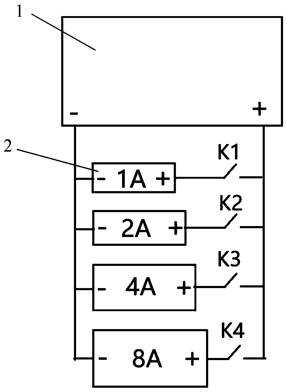
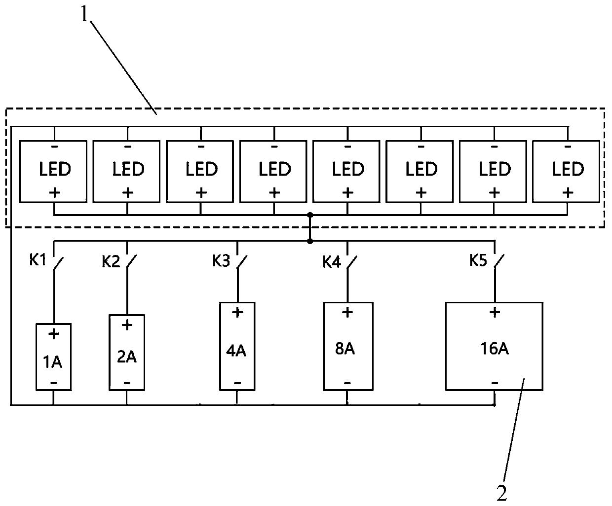
[0017] One of the core concepts of the embodiments of the present invention is to provide a dimming circuit, including a plurality of parallel constant current power sources 2, a control unit and switches connected in series with the constant current power sources 2, and the control unit is connected to the switches. By using the same kind of constant current power supply 2 in parallel, a plurality of constant current power supplies 2 whose output currents are of preset rules are connected together to form a total power supply. Each constant current power supply 2 is connected with a switch, and the output can be controlled by controlling the switch. The total current, so as to achieve the purpose of dimming, low cost, and stable d...


PUM


Abstract

An embodiment of the invention provides a dimming circuit. The dimming circuit comprises a plurality of constant current power supplies connected in parallel, a control unit and switches which are connected with the constant current power supplies in series respectively, and the control unit is connected with the switch. The constant current power supplies of the same type are adopted in parallel,so that a plurality of constant current power supplies with output currents based on a preset rule are connected in parallel to form a general power supply; each constant current power supply is connected with a switch, and the output total current can be controlled by controlling the switches, so that the purpose of dimming is achieved, the cost is low, and the dimming performance is stable.

Description

technical field [0001] The invention relates to the technical field of lighting, in particular to a dimming circuit and a lighting device. Background technique [0002] LED has the advantages of energy saving, long life and environmental protection. In the application of LED, the adjustment of its brightness has a more general application. Adjusting the brightness of LED is not only for energy saving, but also plays an important role in industrial applications. For example, the stability of adjusting LED brightness affects the quality of the UV LED ink curing lamp in the printing industry. The above curing lamp adjusts the UV light intensity of the curing lamp according to the color, thickness, type and printing speed of the ink. If the intensity is insufficient, the ink will not work. If it is too dry, it will burn the paper if it is too strong, and it will cause a fire if it is serious. [0003] The existing LED dimming methods include linear dimming, thyristor dimming an...

Claims


Application Information

Patent Timeline
Patent Type & Authority Applications(China)
IPC IPC(8): H05B33/08H05B44/00
CPCH05B45/00Y02B20/30
Inventor 董翊
Owner 南京伯克利新材料科技有限公司
Learn More