Mpeg video resolution reduction system

A resolution and video technology, applied in the direction of digital video signal modification, television, selective content distribution, etc., can solve the problems of high cost and time-consuming

Inactive Publication Date: 2012-08-29
GENERAL INSTR CORP
View PDF3 Cites 1 Cited by
  • Summary
  • Abstract
  • Description
  • Claims
  • Application Information

AI Technical Summary

Problems solved by technology

However, this straightforward approach is costly in terms of time and processing resources, since the re-encoder

Method used


Image

  • Mpeg video resolution reduction system
  • Mpeg video resolution reduction system
  • Mpeg video resolution reduction system

Examples


Embodiment Construction

[0023] The present invention has been described, for purposes of simplicity and illustration, primarily with reference to exemplary embodiments of the invention. In the following description, numerous specific details are set forth in order to provide a thorough understanding of the present invention. It will be apparent, however, to one of ordinary skill in the art that the present invention may be practiced without limitation to these specific details. In other instances, well-known methods and structures have not been described in detail in order not to unnecessarily obscure the present invention.

[0024] 1. Video resolution reduction system

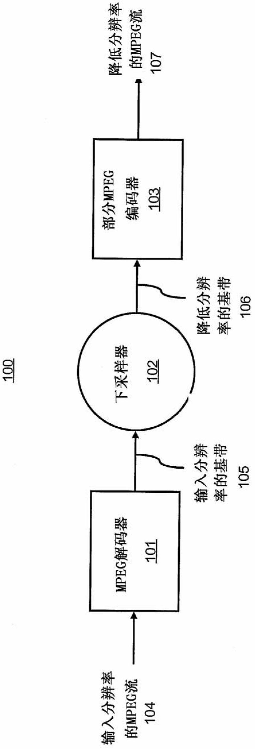
[0025] figure 1 Illustrated is a functional block diagram of an MPEG video resolution reduction system 100 configured to reduce the resolution of an input resolution MPEG stream 104 according to an embodiment. The input resolution MPEG stream 104 may be an MPEG stream. The MPEG stream may be an MPEG-4 Part 10 stream. Although sy...


PUM


Abstract

An MPEG video resolution reduction system includes an MPEG decoder, a down-sampler, and a partial MPEG re-encoder. The MPEG decoder decodes an input resolution MPEG stream to an input resolution baseband, and determines coding information from decoding the input resolution MPEG stream. The down-sampler down-samples the input resolution baseband to a reduced resolution baseband. The partial MPEG re-encoder uses the coding information to encode the reduced resolution baseband to a reduced resolution MPEG stream.

Description

Background technique [0001] ITU-T H.264 / MPEG-4 Part 10 is composed of experts from the International Telecommunication Union Telecommunication Standardization Sector (ITU-T) Video Coding Experts Group (VCEG) and the International Organization for Standardization (ISO) Moving Picture Experts Group (MPEG) International video coding standard developed by the Joint Video Team (JVT). ITU-T H.264 / MPEG-4 Part 10 is also known as MPEG-4AVC (Advanced Video Coding). In MPEG 4 Part 10, interleaved video frames can be constructed and coded (i.e., encoded) in frame mode as a single picture, or in field mode as two separate field picture. MPEG 4 part 10 allows adaptive switching between frame coding mode and field coding mode on a frame-by-frame basis. When compared to previous standards, MPEG 4 part 10 allows high quality video to be achieved at lower bit rates without prohibitive increases in the complexity of applying the standard. [0002] Although MPEG 4 Part 10 is more efficient a...

Claims


Application Information

Patent Timeline
IPC IPC(8): H04N7/26H04N7/50
CPCH04N21/440263H04N19/56H04N19/159H04N19/176H04N19/513H04N19/61H04N19/107H04N19/19H04N19/523H04N19/40
Inventor 孔维颖王利民
Owner GENERAL INSTR CORP
Why Eureka
Try Eureka