A pull-off duplex dlc plug

A plug-and-join technology, applied in the field of pull-off duplex DLC plugs, can solve the problems of inconvenient removal and removal, and achieve the effect of solving the inconvenience of removal and removal

Active Publication Date: 2014-10-22
CHINA AVIATION OPTICAL-ELECTRICAL TECH CO LTD
View PDF5 Cites 0 Cited by
  • Summary
  • Abstract
  • Description
  • Claims
  • Application Information

AI Technical Summary

Problems solved by technology

[0003] The purpose of the present invention is to provide a pull-off duplex DLC plug to solve the problem of inconvenient removal when the existing duplex DLC plugs are densely arranged or arranged in multiple layers

Method used


Image

  • A pull-off duplex dlc plug
  • A pull-off duplex dlc plug
  • A pull-off duplex dlc plug

Examples


Embodiment Construction

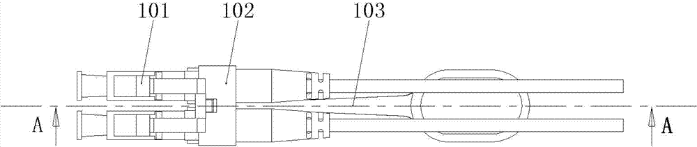
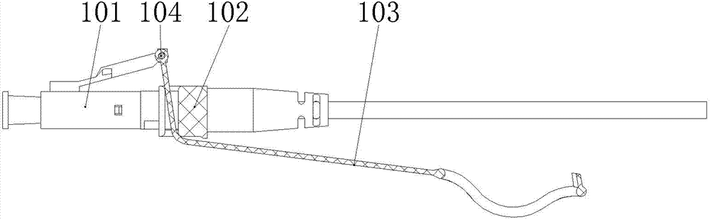
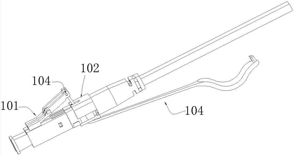
[0021] Pull-off duplex DLC plug embodiment 1 of the present invention, as Figure 1-8 As shown, it consists of two plug units 101 , a positioning housing 102 , a pull cord 103 and a cross bar 104 . The plug unit 101 includes an outer shell 11, a rear sleeve 12 and an optical contact (not shown in the figure) assembled in the outer shell 11. The rear end of the optical contact is connected with a tail cable 13, and the two plug units 101 The outer casings 11 are respectively provided with clips 11-1 on the top surface for clamping with the adapter sockets. The clips 11-1 are elastic, and their front ends are integrally fixed on the corresponding outer casings 11, and their axial ends extend backward and In the process of extending backward, it gradually inclines to the periphery (above) of the plug unit 101. There is a block 11-2 between the two ends of the clip 11-1. The clamping block 11-2 is fitted with an adapted socket; the positioning housing 102 includes a bottom plate ...


PUM


Abstract

The invention relates to a breakaway type duplex data link control (DLC) plug. The breakaway type duplex DLC plug comprises two plug bodies, wherein each plug body comprises an outer shell and a back sleeve which are assembled together in tandem, the two plug bodies are respectively assembled on a positioning shell side by side through respective back sleeves, and the top faces of the outer shells of the two plug bodies are respectively provided with a clip which is fitted with an adaptive socket; a passage running through up and down is formed between the back sleeves of the two plug bodies, an opening running through up and down is formed in the positioning shell corresponding to the passage, a stay cord is arranged in the passage, wherein the stay cord pulls the clips of the two plug bodies so as to unlock the plug and the adaptive socket; after passing through the passage from lower part to upper part, the front end of the stay cord is connected with the corresponding clip, and the back end of the stay cord passes through the lower end of the through slot or the through hole. The problem that DLC plugs are inconvenient to take and unload when being arranged in an intensive or multilayer manner is solved.

Description

technical field [0001] The invention relates to the field of optical connectors, in particular to a pull-off duplex DLC plug. Background technique [0002] The Chinese patent application number 2010201127562 discloses a fiber optic connector, the fiber optic connector includes a protective shell and a duplex DLC plug assembled inside the protective shell, the duplex DLC plug includes two plug monomers, the plug monomer includes The outer casing and the rear sleeve assembled together one after the other. The top surface of the outer casing is respectively provided with clips for clamping with the adapter connector. The clips are elastic, and their front ends are integrated on the top surface of the outer casing. The rear end hangs backwards and gradually slopes towards the top surface of the outer shell. The rear sleeves of the two plugs are inserted side by side on a positioning shell, and the clips on the two shells form a duplex clip. , when it is separated from the adapt...

Claims


Application Information

Patent Timeline
Patent Type & Authority Patents(China)
IPC IPC(8): G02B6/38
Inventor 李小卫
Owner CHINA AVIATION OPTICAL-ELECTRICAL TECH CO LTD
Why Eureka
Try Eureka