
A time base generator and method for providing a first clock signal and a second clock signal

一种时钟信号、发生器的技术,应用在产生/分配信号、仪器、功率的自动控制等方向,能够解决限制等问题

Inactive Publication Date: 2012-09-05
SIEMENS AG
View PDF6 Cites 4 Cited by
  • Summary
  • Abstract
  • Description
  • Claims
  • Application Information

AI Technical Summary

Problems solved by technology

[0011] Another disadvantage comes from the use of digital circuits that limit circuit operation to integers

Method used


Image

  • A time base generator and method for providing a first clock signal and a second clock signal
  • A time base generator and method for providing a first clock signal and a second clock signal
  • A time base generator and method for providing a first clock signal and a second clock signal

Examples


Embodiment Construction

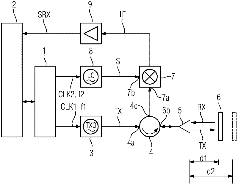
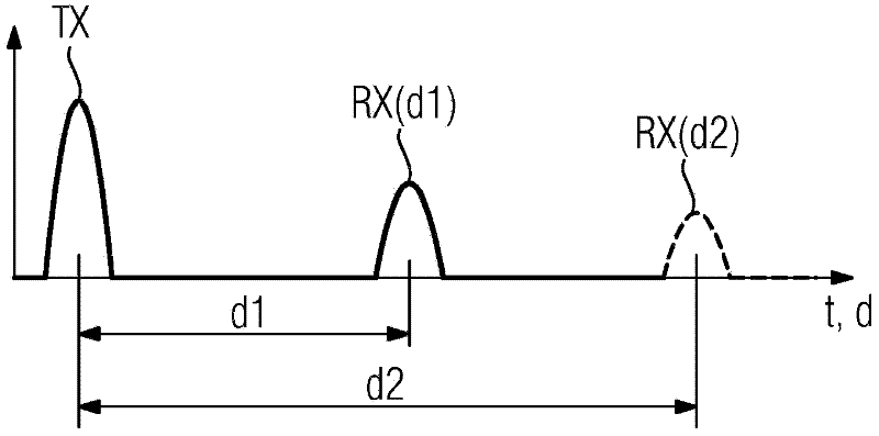
[0030] First refer to figure 1 , which schematically shows a block diagram of the basic components of a pulsed radar ranging system comprising a time base generator 1 according to the invention. The time-base-controlled generator 1 under the control of the microcontroller 2 generates a first clock signal CLK1 at a first clock frequency f1 in the MHz range. The first clock signal CLK1 triggers the transmission oscillator 3 to generate microwave transmission pulses with a pulse repetition rate equal to the first clock frequency f1. The transmission pulse TX may have a duration of 1 ns and a frequency in the GHz range. The transmission oscillator 3 is coupled to a first port 4 a of a directional coupler arrangement in the form of a four-port circulator 4 , the second port 4 b of which is coupled to an antenna 5 . The transmission pulse TX is transmitted via the circulator 4 and the antenna 5 to a target 6 , for example the surface of a filling material in a container. The targ...


PUM


Abstract

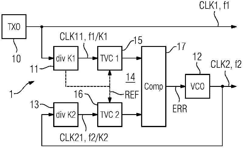
To provide two clock signals (CLK1, CLK2) of slightly different frequencies (f1, f2) with defined time or phase delay, the first clock signal (CLK1) is generated at the first clock frequency (f1), the first clock frequency (f1) is divided by a first integer (K1) to produce a first auxiliary signal (CLK11), the second clock signal (CLK2) is divided by a second integer (K2) to produce a second auxiliary signal (CLK21), an error signal (ERR) is generated by individually weighting and comparing the cycle durations or phasing of the first and second auxiliary signals (CLK11, CLK21), and said second clock signal (CLK2) is generated by means of a voltage-controlled oscillator (17) controlled by said error signal (ERR).

Description

technical field [0001] The invention relates to a time base generator for providing a first clock signal and a second clock signal. [0002] The invention also relates to a method for providing such a first and a second clock signal. Background technique [0003] Pulse radar ranging systems, such as known in US 4,521,778, provide distance or level measurements based on direct measurement of the runtime of microwave pulses transmitted to and reflected from a target, such as the level of filling material in a container surface. Since runtimes for distances of a few meters are in the nanosecond range, specific time transformation procedures are required to enable these short time periods to be measured. Microwave pulses are transmitted to the target at the repetition rate or transmission clock frequency given by the transmission clock generator. In the signal mixer, the received echo pulses reflected from the target are sampled by correlating with a sampling pulse having the...

Claims


Application Information

Patent Timeline
Patent Type & Authority Applications(China)
IPC IPC(8): H03K5/15
CPCG01S7/28G06F1/06H03L7/097H03L7/12H03L7/18
Inventor 乔治·布尔恰
Owner SIEMENS AG
Learn More