Novel sealing ring structure for stop valve

A technology of connecting sleeves and sealing rings, which is applied in the field of hydraulic components, can solve the problems of easy leakage of sealing rings and insufficient tightness of the structure, achieve good connection effect and overcome the effect of insufficient tight connection of connecting sleeves

Inactive Publication Date: 2012-09-12
郑红侠
View PDF0 Cites 0 Cited by
  • Summary
  • Abstract
  • Description
  • Claims
  • Application Information

AI Technical Summary

Problems solved by technology

[0003] The purpose of the present invention is to provide a new shut-off valve joint sleeve sealing

Method used


Image

  • Novel sealing ring structure for stop valve
  • Novel sealing ring structure for stop valve

Examples


Embodiment Construction

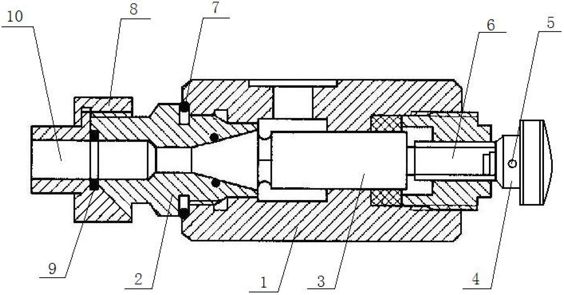
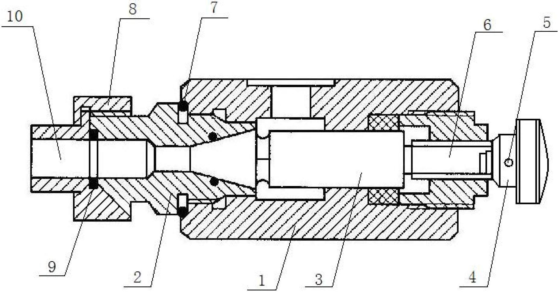
[0009] The sealing ring structure of the connecting sleeve has a valve body (1), a valve seat (2) is connected to the left side of the valve body (1), and a rear sealing ring (7) is arranged between the valve seat (2) and the valve body (1) Sealing; there is an adjustment wheel (4) at the rear end of the valve body (1), and the adjustment wheel (4) is installed on the right end of the valve core (3) through threaded pins (5) and threads (6); on the valve body (1) There is a connecting sleeve (10) on the valve seat (2) at the front end, and the connecting sleeve (10) is installed on the right end of the valve seat (2) through the coupling sleeve (8). A front sealing ring (9) is arranged between the sleeves (8) for sealing.


PUM


Abstract

The invention relates to a novel sealing ring structure for a stop valve. The novel sealing ring structure for the stop valve is provided with a valve body, wherein a valve seat is connected with the left side of the valve body, a back sealing ring is arranged between the valve seat and the valve body for sealing, the back end part of the valve body is provided with a regulating wheel, the regulating wheel is arranged at the right end part of the valve core through a threaded pin and screw threads, a connecting sleeve is arranged on the valve seat arranged at the front end part of the valve body, the connecting sleeve is arranged at the right end part of the valve seat through a combining sleeve, and a front sealing ring is arranged between the connecting sleeve and the combining sleeve for sealing.

Description

technical field [0001] The invention relates to a sealing ring structure of a connecting sleeve, in particular to a novel structure of a sealing ring of a connecting sleeve of a cut-off valve, belonging to the technical field of hydraulic components. Background technique [0002] The sealing ring structure of the stop valve connecting sleeve is an important hydraulic component in the hydraulic system. Its main function is to play the role of connection and sealing. In the existing structure of the stop valve connecting sleeve, the connection of the stop valve connecting sleeve is not tight enough. , The defect that the sealing ring is easy to leak. Contents of the invention [0003] The purpose of the present invention is to provide a new shut-off valve joint sleeve sealing ring structure which has good connection effect and is not easy to leak. The loop is prone to leaking defects. [0004] The technical solution adopted by the present invention to solve the technical p...

Claims


Application Information

Patent Timeline
IPC IPC(8): F16K1/46
Inventor 郑红侠
Owner 郑红侠
Why Eureka
Try Eureka