
Double-spiral-groove drill rod coated with optical fibers and communication drilling machine

A helical groove and double helix technology, which is applied in the field of double helical groove coated optical fiber drill pipes and communication drilling rigs, can solve the problems of unable to guarantee the safety of communication optical fibers, easy to squeeze and wear optical fibers, etc., to overcome the small signal capacity and the difficulty of processing Big, Applicable Effects

Pending Publication Date: 2022-07-15
XIAN RES INST OF CHINA COAL TECH& ENG GROUP CORP
View PDF0 Cites 0 Cited by
  • Summary
  • Abstract
  • Description
  • Claims
  • Application Information

AI Technical Summary

Problems solved by technology

[0003] In view of the deficiencies in the prior art, the purpose of the present invention is to provide a double helical groove coated optical fiber drill rod and a communication drilling machine, which solves the problem that the drill rod and the external optical fiber of the drill tool in the prior art are extremely easy to rotate during the drilling process. Squeeze and wear out the optical fiber, which cannot guarantee the safety of the communication optical fiber itself

Method used


Image

  • Double-spiral-groove drill rod coated with optical fibers and communication drilling machine
  • Double-spiral-groove drill rod coated with optical fibers and communication drilling machine
  • Double-spiral-groove drill rod coated with optical fibers and communication drilling machine

Examples


Embodiment 1

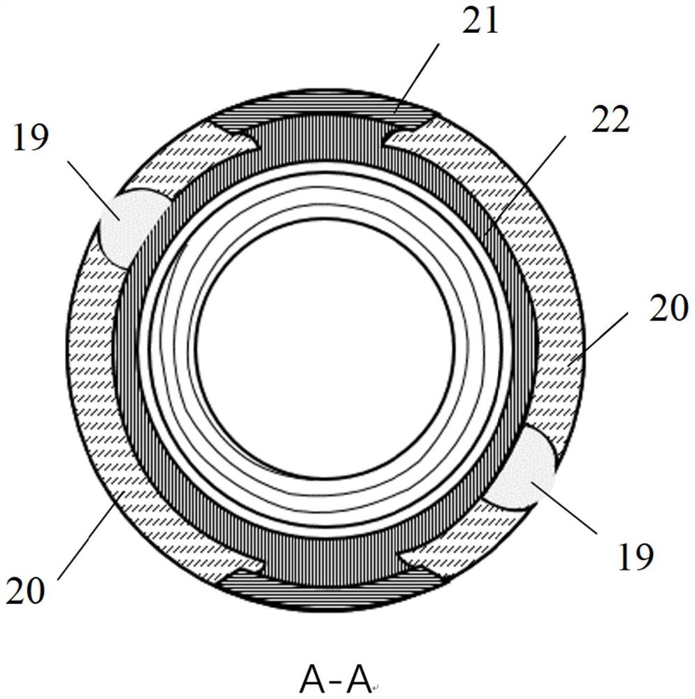
[0053] Follow the above technical solutions, such as Figure 1 to Figure 7 As shown, a double helical groove coated fiber optic drill rod comprises a helical groove drill rod 1 and a wire-passing drill rod joint 2 connected to one end of the helical groove drill rod 1, and the helical groove drill rod 1 spirals along its outer surface. A first helical trimming groove 3 is arranged, and the first helical trimming groove 3 is embedded in and penetrates the outer surface of the helical groove drill rod 1;

[0054] The wire-passing drill pipe joint 2 is spirally arranged with a second helical edge trimming groove 4 along its outer surface, and the second helical edge-receiving groove 4 is embedded in the outer surface of the wire-passing drill pipe joint 2;

[0055] The first helical edge trimming groove 3 and the second helical edge trimming groove 4 are provided through.

[0056] The first helical edge trimming groove 3 and the second helical edge trimming groove 4 are used for a...

Embodiment 2

[0100] Follow the above technical solutions, such as Figure 8 As shown in the figure, a communication drilling rig includes a drilling rig 16, on which the double helical groove outer-coated fiber optic drill rod as described in Embodiment 1 is installed; Signal instrument 18. Drilling rig 10 is used to provide power. The number of double helical groove outer-coated fiber optic drill rods installed on the drilling rig 10 may be multiple.

[0101]In specific use, select one or more sections of double helical groove covered fiber optic drill pipe according to the needs, install the drill pipe joints, drill bits and signal instruments through the wire, and snap the hole outside the double helical groove covered fiber optic drill pipe. Drilling spool, the optical fiber is led out of the hole, that is, the spool is clamped while drilling, and the optical fiber is connected to the signal instrument through the first spiral edge groove, the second spiral edge groove and the throug...


PUM


Abstract

The invention discloses a drill rod with double spiral grooves coated with optical fibers and a communication drilling machine, the drill rod comprises a spiral groove drill rod and a wire passing drill rod joint connected to one end of the spiral groove drill rod, the spiral groove drill rod is spirally provided with a first spiral edge closing groove along the outer surface of the spiral groove drill rod, and the first spiral edge closing groove is embedded into and penetrates through the outer surface of the spiral groove drill rod; a second spiral edge closing groove is spirally formed in the outer surface of the wire passing drill rod connector and embedded into the outer surface of the wire passing drill rod connector. And the first spiral edge-closing groove and the second spiral edge-closing groove are arranged in a penetrating manner and are used for arranging optical fibers. According to the invention, the long-distance whole optical fiber fitting drilling tool can be quickly retreated along with drilling, the problems of multi-joint connection and small signal capacity of a buried wire in a conventional communication drilling rod are solved, and the problem of safe and stable transmission of large-capacity signals while drilling of the drilling tool in a coal mine underground drill hole is solved.

Description

technical field [0001] The invention relates to the technical field of signal transmission of underground drilling tools in coal mines, in particular to a double-spiral groove outer-coated fiber-optic drill pipe and a communication drilling rig. Background technique [0002] With the overall progress and development of coal industry technology, coal mine underground drilling has higher and higher requirements for drilling trajectory control and identification of geological conditions in the hole. The problem of timely transmission of big data. In traditional communication drilling rigs, each drill pipe has an independent built-in cable. When the drill pipe is connected, the cable is connected by the built-in joint. Due to the underground working conditions of the coal mine and the efficiency of loading and unloading the drill pipe during the drilling construction, each drill pipe has an independent built-in optical fiber, etc. Large-capacity communication cables are unreali...

Claims


Application Information

Patent Timeline
Patent Type & Authority Applications(China)
IPC IPC(8): E21B17/00G02B6/44
CPCE21B17/00G02B6/44
Inventor 赵继展张俭龙威成陈志胜董敏涛王晨阳
Owner XIAN RES INST OF CHINA COAL TECH& ENG GROUP CORP
Learn More