
Fatigue test equipment for flat spiral springs and method for performing fatigue test by aid of fatigue test equipment

A flat scroll spring, fatigue test technology, applied in the direction of applying repetitive force/pulse force to test the strength of materials, can solve the problems of high motor requirements, re-calibration, poor versatility, etc., to achieve strong versatility and easy adjustment. Effect

Active Publication Date: 2012-09-12
JAPHL POWERTRAIN SYST
View PDF5 Cites 24 Cited by
  • Summary
  • Abstract
  • Description
  • Claims
  • Application Information

AI Technical Summary

Problems solved by technology

[0004] The existing spring fatigue test equipment and its test method patent (patent number: 201010140087.4) has the following disadvantages: 1) Although this patent can use a smaller DC motor to achieve the purpose of driving, if it is necessary to increase the number of planar scroll springs tested , it is necessary to re-check the torque of the motor; 2) The direction of rotation of the planar scroll springs participating in the test is consistent from the initial state to the state of the maximum rotation angle, that is, when the spring needs to store energy, the torque that needs to be provided must be The sum of the torques to overcome all planar scroll springs
High requirements on the motor, waste of resources; 3) This patent adopts a special cam-shaped wire structure, although the preload angle of the plane scroll spring can be adjusted, but the working angle range of the plane scroll spring cannot be easily adjusted Yes, a new cam-shaped wire structure must be redesigned to achieve
In summary, due to the above-mentioned shortcomings in the equipment of the prior art, the versatility of the equipment is relatively poor

Method used


Image

  • Fatigue test equipment for flat spiral springs and method for performing fatigue test by aid of fatigue test equipment
  • Fatigue test equipment for flat spiral springs and method for performing fatigue test by aid of fatigue test equipment
  • Fatigue test equipment for flat spiral springs and method for performing fatigue test by aid of fatigue test equipment

Examples


Embodiment Construction

[0032] Below with reference to the accompanying drawings, through the description of the embodiments, the specific embodiments of the present invention, such as the shape, structure, mutual position and connection relationship between the various parts, the role and working principle of the various parts, etc., will be further described. Detailed instructions:

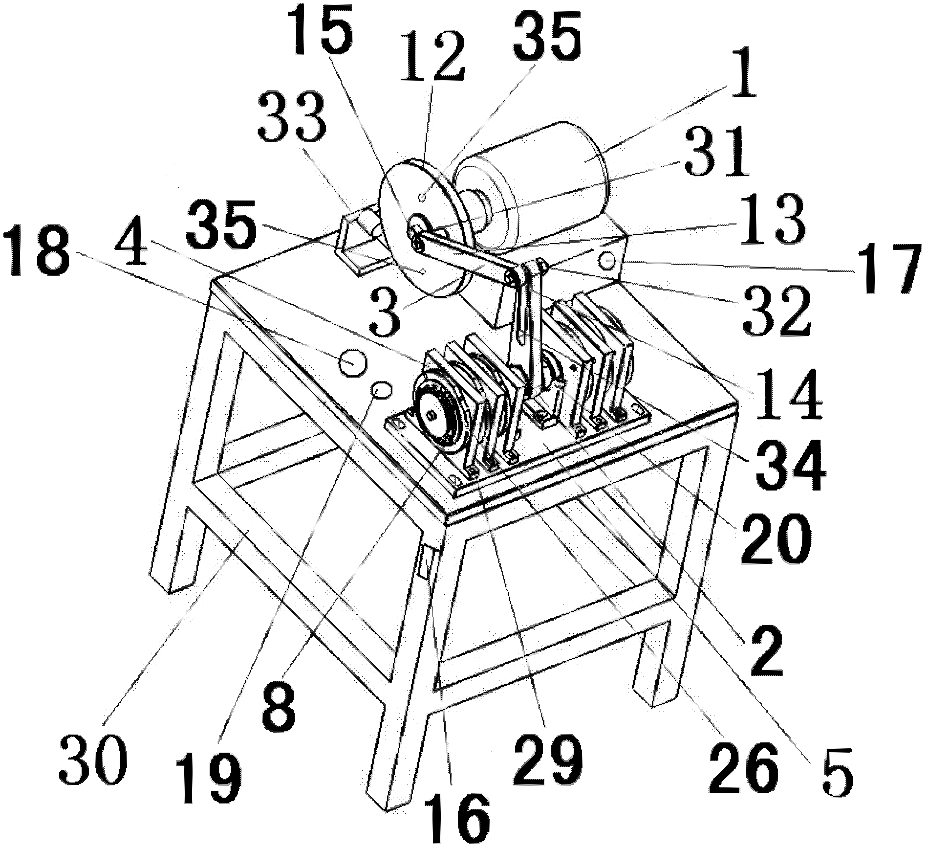
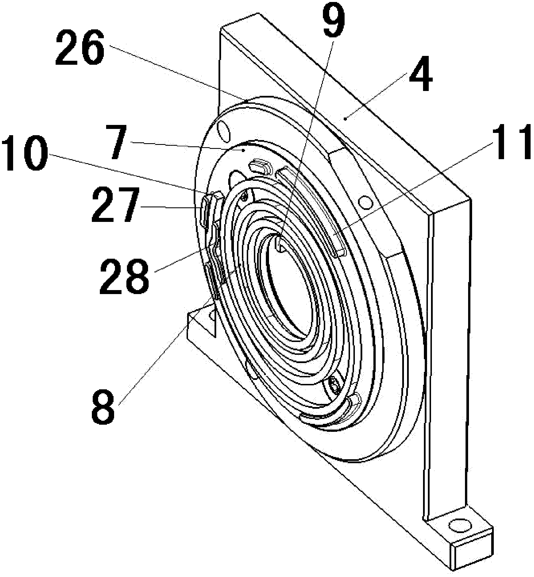
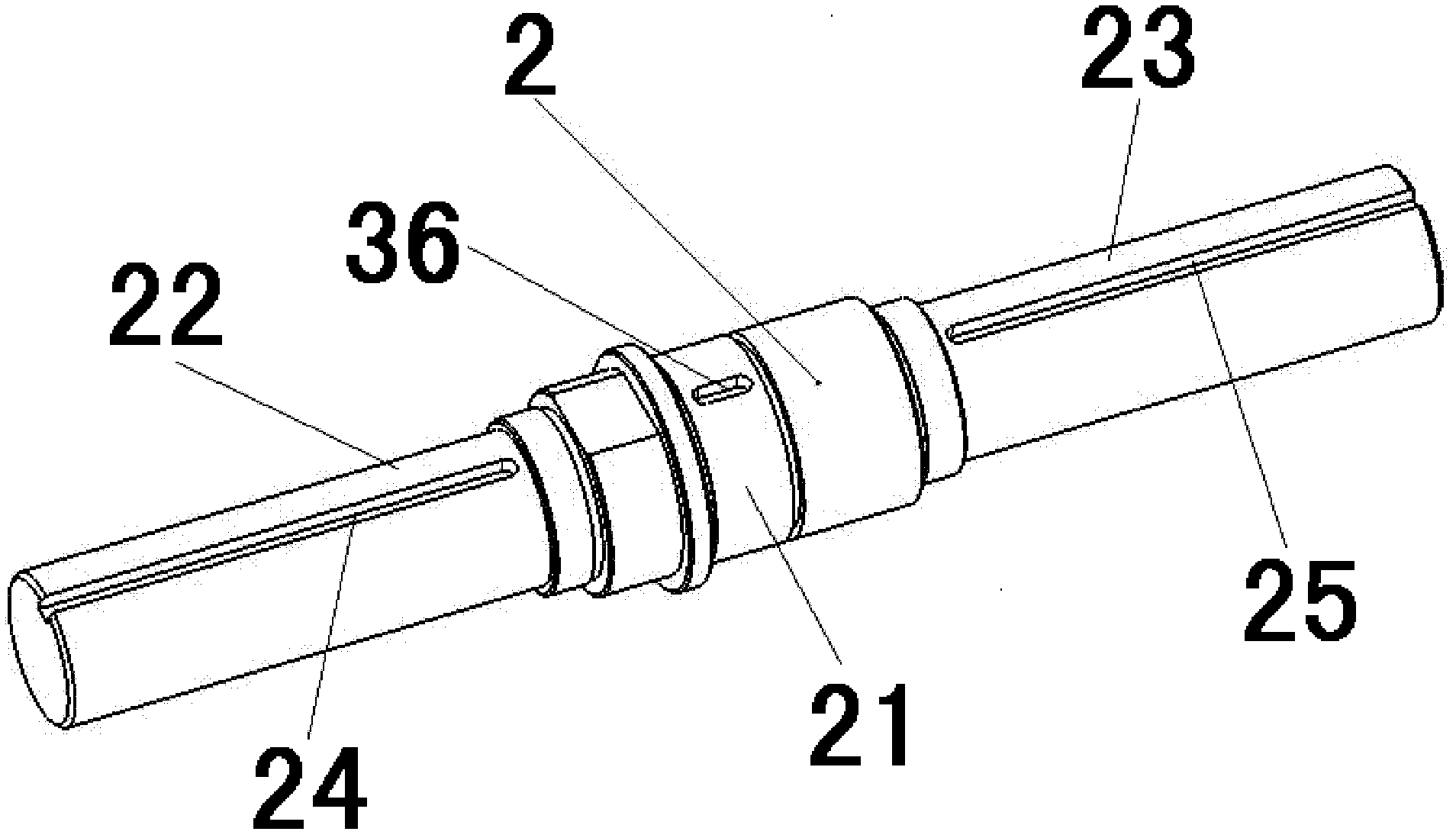
[0033] as attached figure 1 - attached Figure 5 As shown, the present invention is a kind of planar scroll spring fatigue test equipment, and described planar scroll spring fatigue test equipment comprises drive motor 1, rotating shaft 2, and the crank linkage mechanism 3 that drives rotating shaft 2 to do reciprocating rotation by drive motor 1 , the rotating shaft 2 is covered with a plurality of supporting plates 4 arranged according to the gaps, the supporting plates 4 are fixed on the base 5, the rotating shaft 2 is provided with a keyway 6, and each supporting plate 4 is provided with a scroll spring When the ...


PUM


Abstract

The invention provides fatigue test equipment for flat spiral springs, is applied to the technical field of fatigue test for spiral springs, and also relates to a method for testing by the aid of the test equipment. A plurality of support plates (4) which are arranged at intervals are sleeved on a rotary shaft (2) of the fatigue test equipment for flat spiral springs, and are fixed onto a base (5), key slots (6) are disposed on the rotary shaft (2), a spiral spring mounting plate (7) is arranged on each support plate (4), a bent portion (9) of the inner end of each spiral spring (8) is clamped in the corresponding key slot (6), and the outer end (10) of each spiral spring (8) is clamped on a check block (11) on the corresponding spiral spring mounting plate (7). The fatigue test equipment for the flat spiral springs has the advantage that the purpose of driving can be achieved by the aid of low torque, and in other word, a direct-current motor can be selectively used as a power source.

Description

technical field [0001] The invention belongs to the technical field of scroll spring fatigue testing, more specifically, relates to a plane scroll spring fatigue testing equipment, and the present invention also relates to a fatigue testing method using the plane scroll spring fatigue testing equipment. Background technique [0002] Planar scroll spring is a kind of spring that is wound into planar spiral wire with slender spring material. One end of the spring is fixed, and when torque is applied to the other end, the spring material produces bending elastic deformation under the action of the bending moment, causing the spring to twist in its own plane. Planar scroll springs are mainly used to provide rotational torque, store energy through the torsion of the spring itself, and release energy as needed to achieve action. [0003] According to the needs of different working conditions, the planar scroll spring must be able to achieve repeated and reliable storage torque an...

Claims


Application Information

Patent Timeline
Patent Type & Authority Applications(China)
IPC IPC(8): G01N3/38
Inventor 张闯范礼李雪涛曹志诚丁万龙
Owner JAPHL POWERTRAIN SYST
Learn More