Supercharge Your Innovation With Domain-Expert AI Agents!

Flat clinch type stapler

A stapler and nail foot technology, which is applied in the directions of staple staple tools, manufacturing tools, etc., can solve the problems of longitudinal bending of the through-end of the staples, guide of the staples, etc.

Inactive Publication Date: 2012-09-12
KOKUYO CO LTD
View PDF5 Cites 2 Cited by
  • Summary
  • Abstract
  • Description
  • Claims
  • Application Information

AI Technical Summary

Problems solved by technology

Therefore, in the final stage of bending, it is difficult to sufficiently push the root portion of the through end of the staple toward the paper direction, and the binding may be completed in a state where the root portion bulges slightly away from the paper. bad situation
[0004] Such a problem can also be alleviated by setting the inclination of the abutting surface to be relatively gentle in advance, but if this is the case, it will be difficult to guide the top end of the staple to the inside smoothly at the initial stage of bending, and there is a tendency to cause the staple to be bent. Difficulties such as the problem of vertical bending at the through end

Method used


Image

  • Flat clinch type stapler
  • Flat clinch type stapler
  • Flat clinch type stapler

Examples


Embodiment Construction

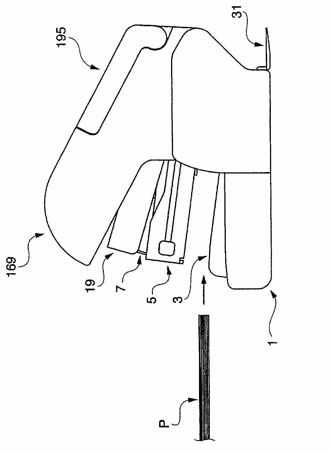
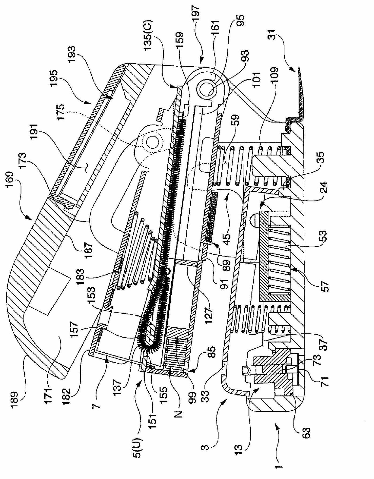
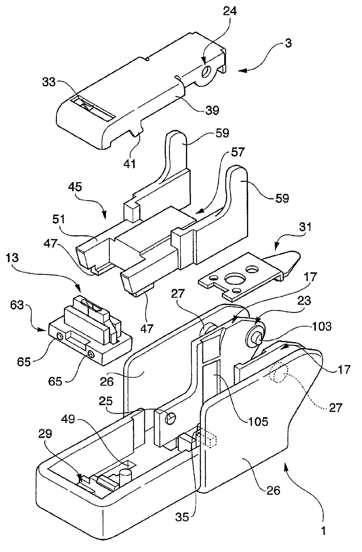
[0037] Below, while referring to the attached Figure 1 One embodiment of the present invention will be described.

[0038] The flat foot type stapler, such as Figure 1 to Figure 15 As shown, it has: a base 1; a paper loading table 3, which is pivotally connected to the base 1, and is used to add paper P to be bound; a staple box 5, which is arranged opposite to the paper loading table 3 and holds staples N; push knife 7, it pushes out the staple N held in the staple box 5 toward the paper carrier 3 direction; anvil 13, it is used to pass through the abutting surface 9 for bending or the abutting surface 11 for forming will be used by the abutting surface 11 The push knife 7 pushes out and bends the penetration end N1 of the staple N that has penetrated the paper P; After being engaged with the abutting surface 9 for bending, it is engaged with the abutting surface 11 for forming.

[0039] base 1 as Figure 1 to Figure 3 as well as Figure 5 As shown, it is molded by syn...


PUM


Abstract

PROBLEM TO BE SOLVED: To provide a flat clinch type stapler capable of bending and binding a staple in a flat state without causing buckling or the like to the staple. ; SOLUTION: The flat clinch type stapler includes a paper table 3 for attaching papers P to be bound, a magazine 5 disposed opposite to the paper table 3 and holding the staple N, a pushing blade 7 for pushing the staple N held in the magazine 5 toward the direction of the paper table 3, an anvil 13 in which either bending abutting faces 9 or forming abutting faces 11 bend penetrated end portions N1 of the staple N which is pushed by the pushing blade 7 and has penetrated the papers P, and an abutting face switching mechanism that engages the staple N with the forming abutting faces 11 after engaging the staple N with the bending abutting surfaces 9 at the time of bending action by the anvil 13.

Description

technical field [0001] The present invention relates to a flat clinch type stapler for binding paper. Background technique [0002] Conventionally, as such a stapler, a stapler equipped with the following components is known (for example, refer to Patent Document 1): a paper table for adding paper to be stapled; a staple magazine, which is opposed to the paper table arranging and holding staples; a pusher for pushing out the staples held by the staple magazine toward the paper stage; and a chopping board for pushing out and penetrating the through ends of the staples of the paper by the pusher Bend at the bottom. [0003] However, in a conventional stapler, an abutment surface for guiding and bending the penetrating end portion of the staple is formed on the tip end of the fixed cutting board. The abutting surface is inclined in a direction that guides the leading end of the staple inward with respect to the paper. Therefore, in the final stage of bending, it is difficult...

Claims


Application Information

Patent Timeline
IPC IPC(8): B25C5/02
CPCB25C5/025
Inventor 篠原胜
Owner KOKUYO CO LTD
Features
  • R&D
  • Intellectual Property
  • Life Sciences
  • Materials
  • Tech Scout
  • Unparalleled Data Quality
  • Higher Quality Content
  • 60% Fewer Hallucinations
Learn More