
Vehicle Equipment Mounting Structure

A vehicle and equipment technology, applied in the field of vehicle equipment carrying structure, can solve the problem of low loss, achieve the effects of high degree of freedom, cost reduction, and elimination of adverse conditions

Active Publication Date: 2015-11-25
TOYOTA JIDOSHA KK +1
View PDF10 Cites 0 Cited by
  • Summary
  • Abstract
  • Description
  • Claims
  • Application Information

AI Technical Summary

Problems solved by technology

[0006] In addition, since the auxiliary battery has a relatively low voltage of 12 volts, the loss due to damage is low, but it is desired to minimize the loss of the power control device that controls the high voltage of several hundred volts

Method used


Image

  • Vehicle Equipment Mounting Structure
  • Vehicle Equipment Mounting Structure
  • Vehicle Equipment Mounting Structure

Examples


Embodiment Construction

[0032] Hereinafter, the best mode (hereinafter, referred to as embodiment) for implementing the present invention will be described with reference to the drawings.

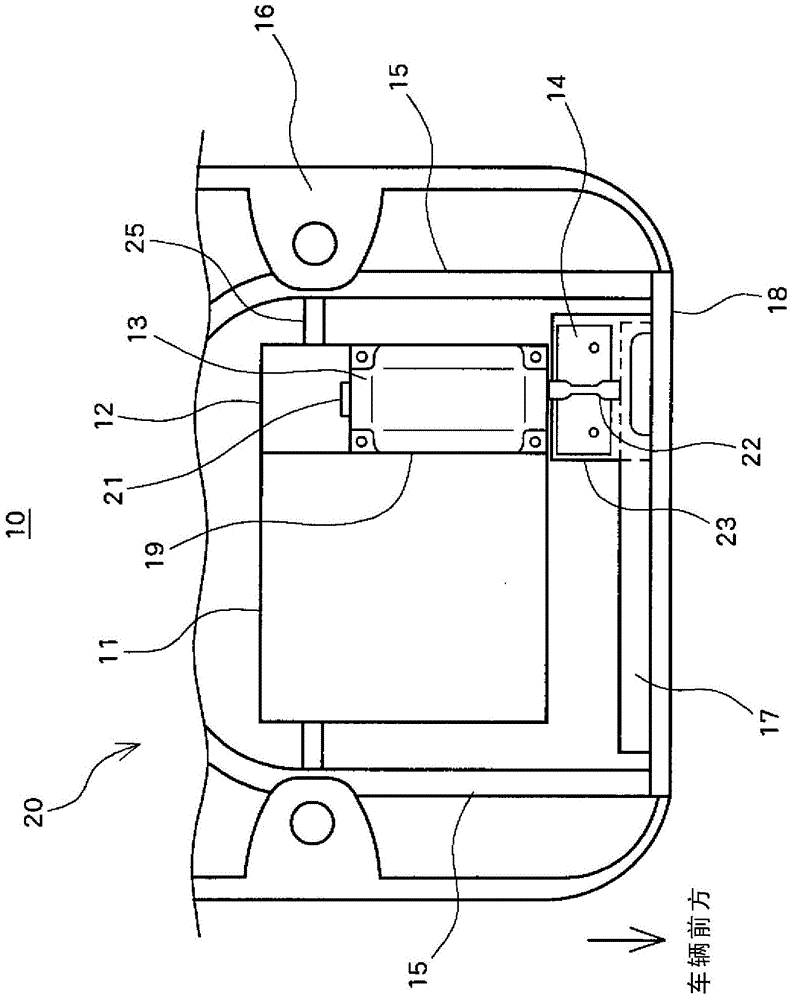
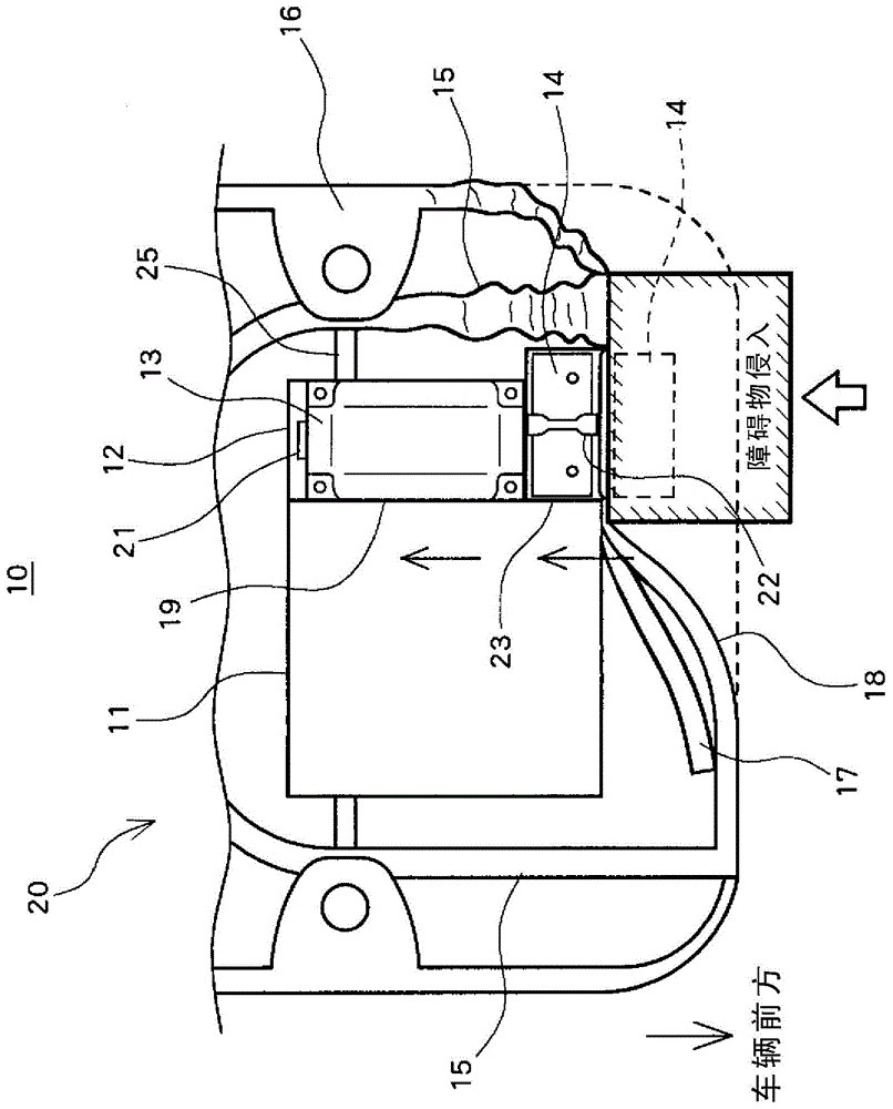
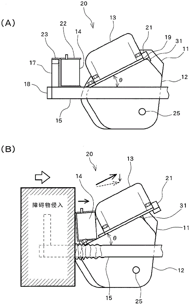
[0033] figure 1 An overview of the vehicle device installation structure in the engine compartment 20 of the hybrid vehicle 10 is shown, and the figure 1The vehicle device mounting structure will be briefly described. The engine compartment 20 is located in front of the passenger compartment of the hybrid vehicle 10 and includes a side member (Side member) 15 serving as a vehicle frame member of the hybrid vehicle 10 , a front cross member (Front cross member) 18 connecting the two side members 15 , and a connecting member. The spring support 16 on the side member 15 , the auxiliary battery 14 arranged on the vehicle front side of the PCU 13 and attached to the front cross member 18 via the support base 23 and the fixing member 22 , and the radiator attached to the front cross member 18 17. The engine 11 and the...


PUM


Abstract

The present invention comprises side members (15), which are vehicular skeleton members of a hybrid vehicle (10); a front cross member (18) for connecting the two side members (15); spring supports (16) connected to the side members (15); an auxiliary battery arranged further towards the vehicle front relative to a PCU (13) and attached to the front cross member (18) via a support platform (23) and a securing piece (22); a radiator (17) attached to the front cross member (18); a motor case (12) and an engine (11) connected to the vehicular skeleton member via an engine mount; an axle (25) extending from the motor case (12); and a PCU (13) connected to the motor case (12) via a guide plate (19) and a linkage bolt. Thus, there is provided a vehicular instrument-mounting structure capable of inhibiting collision of a power control device or other vehicle-mounted instrument with another member, and inhibiting damage caused to the power control device or other vehicle-mounted instrument during a vehicle collision.

Description

technical field [0001] The present invention relates to a vehicular device-mounted structure equipped with a power control device for controlling a rotating electric machine and an auxiliary battery for supplying power to a control unit of the power control device, the vehicle device-mounted structure being arranged in an area provided in front of a vehicle compartment The motor housing that houses the rotating electric machine that drives the vehicle. Background technique [0002] Conventionally, there are known electric vehicles that drive the vehicle with the driving force of a rotating electrical machine such as a motor generator, hybrid vehicles that combine an engine as an internal combustion engine and a rotating electrical machine, and fuel cells that drive the vehicle with electric power generated by a fuel cell. cars etc. Such a vehicle has an electric power control device that has a boost converter, an inverter, etc., receives supply of electric power from a main...

Claims


Application Information

Patent Timeline
Patent Type & Authority Patents(China)
IPC IPC(8): B60R16/04
CPCB62D21/155B60K1/00B60R16/04B60Y2200/92B60Y2306/01
Inventor 堀田幸司山中贤史堀田丰
Owner TOYOTA JIDOSHA KK
Learn More