
Suction cup

A suction cup and sealing area technology, applied in suction cups, connecting components, mechanical equipment, etc., can solve problems such as shell damage and user injury, and achieve the effects of simple installation, improved operation, and reliable support

Active Publication Date: 2012-09-12
BSH BOSCH & SIEMENS HAUSGERAETE GMBH
View PDF6 Cites 5 Cited by
  • Summary
  • Abstract
  • Description
  • Claims
  • Application Information

AI Technical Summary

Problems solved by technology

This can lead, for example, to damage to the housing or, in the worst case, to injury to the user

Method used


Image

  • Suction cup
  • Suction cup
  • Suction cup

Examples


Embodiment Construction

[0026] In the following description of the present invention, the same reference numerals indicate the same or comparable parts.

[0027] The features disclosed in the previous specification, claims and drawings are of great significance to the realization of different design solutions of the present invention not only individually but also in any combination.

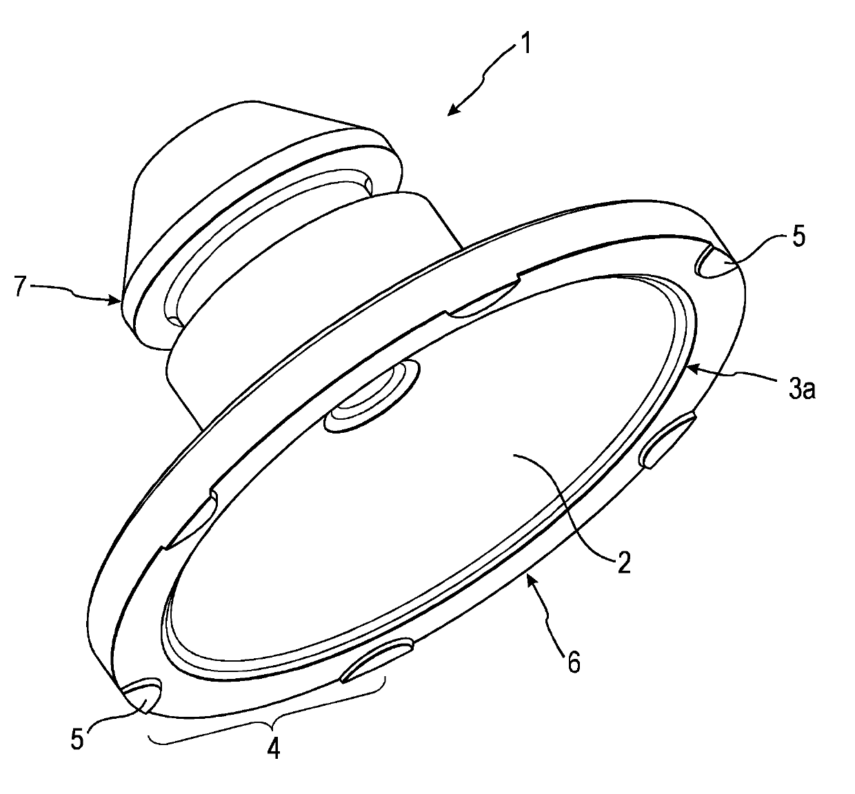
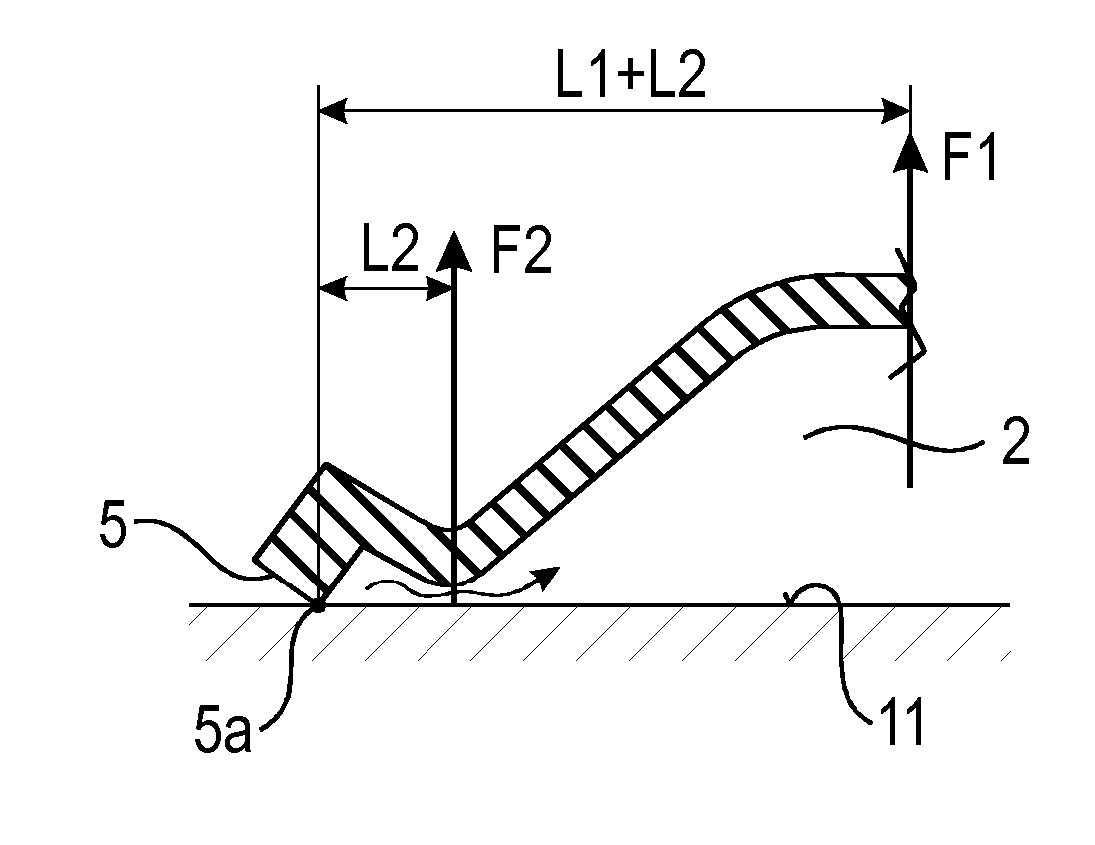
[0028] figure 1 A suction cup according to the invention is shown. The suction cup 1 includes a negative pressure chamber or suction housing 2 and a sealing area 3. The suction cup is usually pressed against the contact surface 11, and the air can escape from the negative pressure chamber by the applied pressing force. The suction cup 1 is made of an elastic-flexible material, especially rubber, so that the negative pressure chamber 2 can be deformed, so that air can be discharged. After the air escapes from the negative pressure chamber, a vacuum is formed, which can be maintained with respect to the environment by means...


PUM


Abstract

The invention relates to a suction cup (1) for applying to a contact surface (11), comprising a vacuum chamber (2) for implementing a retention force. The vacuum chamber (2) is defined by a peripheral sealing area (3) for interacting with the contact surface (11). The suction cup (1) comprises at least one means (4) disposed on the sealing area (3) for reducing a release force that counteracts the retention force.

Description

Technical field [0001] The invention relates to a suction cup for mounting on a contact surface. The suction cup includes a negative pressure chamber for generating a holding force, and the negative pressure chamber is defined by a surrounding sealing area in order to interact with the contact surface. Background technique [0002] Such suction cups have many applications in practice. Suction cups can be used as fasteners for household use, for example, or another application field of suction cups is automated production, where different components or parts must be moved. Suction cups are also known as support aids for glass plates in order to be able to provide suitable support handles for bulky glass plates. The suction cup is usually installed on a smooth surface and forms a suction device in which the highest possible vacuum should be formed and a relatively wide contact surface should be formed on the smooth base. The suction cup is usually made of a rubber body and is pre...

Claims


Application Information

Patent Timeline
Patent Type & Authority Applications(China)
IPC IPC(8): F16B47/00
CPCF16B47/00
Inventor R.萨贝克M.乌普拉茨尼克
Owner BSH BOSCH & SIEMENS HAUSGERAETE GMBH
Learn More