
Weld detecting method and weld detecting apparatus

A detection method and weld area technology, which is applied in the field of weld area detection and weld area detection devices, can solve problems such as excessive time, and achieve the effect of reducing time spent and low cost

Inactive Publication Date: 2012-09-12
TOYOTA JIDOSHA KK
View PDF8 Cites 0 Cited by
  • Summary
  • Abstract
  • Description
  • Claims
  • Application Information

AI Technical Summary

Problems solved by technology

That is, it takes more time to inspect the weld zone

Method used


Image

  • Weld detecting method and weld detecting apparatus
  • Weld detecting method and weld detecting apparatus
  • Weld detecting method and weld detecting apparatus

Examples


Embodiment Construction

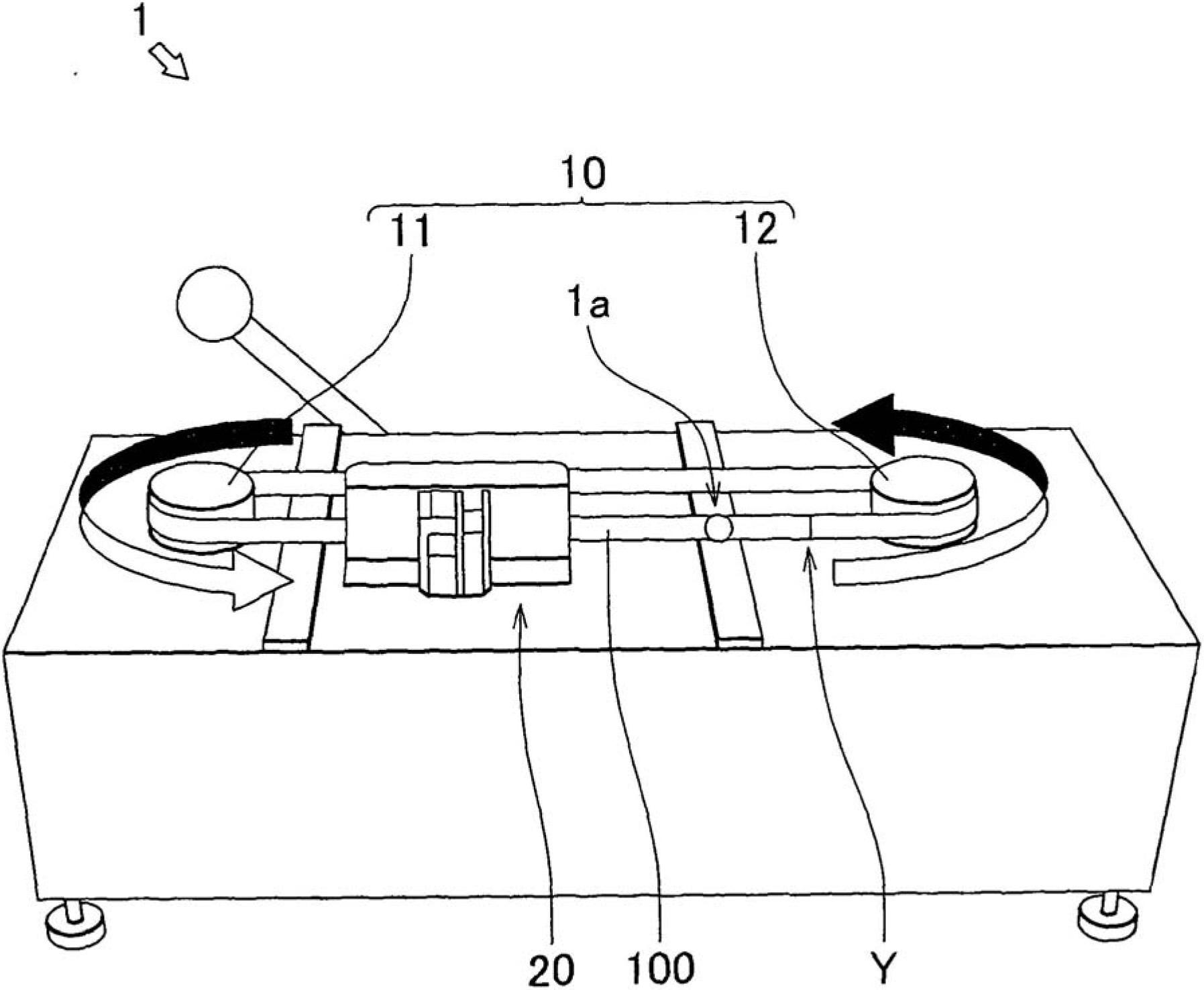
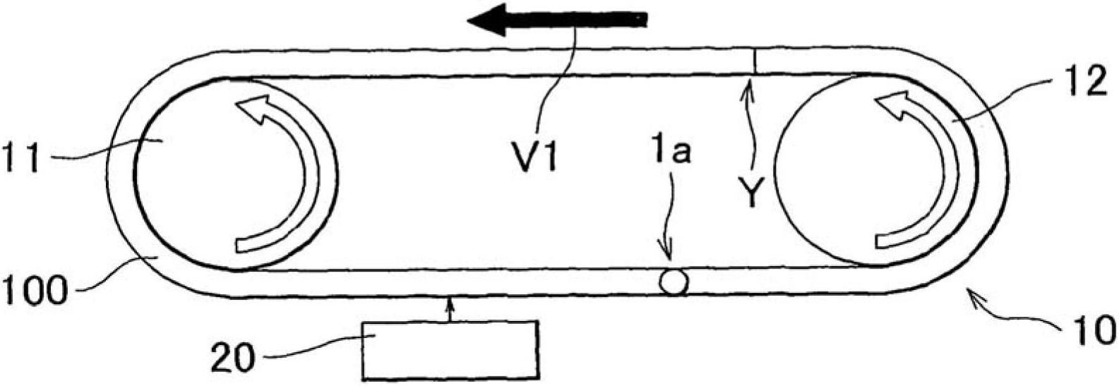
[0035] Hereinafter, a weld zone detection device 1 for detecting a weld zone Y using the weld zone detection method according to the first exemplary embodiment will be described with reference to the drawings.

[0036] Such as Figure 1 to Figure 10 As shown, the bead region detecting device 1 detects the bead region Y on the work that is elongated after being welded by performing rolling, circumferential adjustment, etc. after welding. Some examples of such workpieces 100 are: a metal ring in which both ends of a band-shaped metal plate have been joined together by welding; and a joined metal strip in which ends of a plurality of band-shaped metal plates have been joined together by welding.

[0037] Incidentally, when detecting a weld zone on a workpiece formed in a ring shape such as a metal ring, the weld zone detecting device 1 structure is different.

[0038] Hereinafter, explanation will be given of the weld zone detecting device 1 when detecting the weld zone Y on th...


PUM


Abstract

A weld detecting method that detects a weld on a work includes: obtaining in advance at least one correlation, from among a correlation between a width of the neck and an amount of elongation of the work and a correlation between the width of the neck and an amount of change in at least one of a sheet thickness and a sheet width of the work before and after elongation of the work, and calculating the width of the neck based on the at least one correlation by obtaining at least one of the sheet thickness, the sheet width, or the amount of elongation of the work from the obtained at least one correlation; setting a conveying speed, according to the calculated width of the neck; and detecting the neck by measuring the sheet width of the work at predetermined intervals, while conveying the work at the set conveying speed.

Description

technical field [0001] The invention relates to a weld seam detection method and a weld seam detection device for detecting the position of a weld seam region on a workpiece. Background technique [0002] For example, when a workpiece is formed by joining both end portions of the plate-like portion together by welding, a weld zone is formed on the workpiece. On the workpiece, properties such as hardness in the weld zone differ from those at other parts. Therefore, it is necessary to detect the position of the bead area in order to check only the bead area or to perform processing on a portion other than the bead area. However, when a worker inspects a bead area on a workpiece that has been elongated by rolling or the like by visual confirmation, it is extremely difficult to discern the position of the bead area, so inspection takes longer. Examples of such workpieces include metal rings and metal strips. [0003] For example, Japanese Patent Application Publication No. 61...

Claims


Application Information

Patent Timeline
Patent Type & Authority Applications(China)
IPC IPC(8): G01B5/00G01N19/08
CPCG01B5/0037G01B11/046G01N19/08
Inventor 福岛贤人铃木裕二岩崎进一
Owner TOYOTA JIDOSHA KK
Learn More