Water sprinkling device of plant cultivation machine

A technology of sprinkler and cultivator, applied in cultivation, soilless cultivation, botanical equipment and methods, etc., can solve the problem that water droplets cannot reach plants in the distance, the water lifting height and amount are low, and the water level difference of the water platform is small. and other problems, to avoid uneven watering, increase the water lifting height, and improve the water lifting height.

Inactive Publication Date: 2012-09-19
GUANGZHOU XINGRONG BIOLOGICAL TECH
View PDF11 Cites 2 Cited by
  • Summary
  • Abstract
  • Description
  • Claims
  • Application Information

AI Technical Summary

Problems solved by technology

[0003] However, the above-mentioned sprinkling device is limited by the working mechanism, and its water-lifting height and water-lifting capacity are all on the low side, and it takes a long time to sprinkle the plants in the cultivator; and after the plants grow tall, due to the water-lifting height Lower, the sprinkled water droplets are more likely

Method used


Image

  • Water sprinkling device of plant cultivation machine
  • Water sprinkling device of plant cultivation machine
  • Water sprinkling device of plant cultivation machine

Examples


Example Embodiment

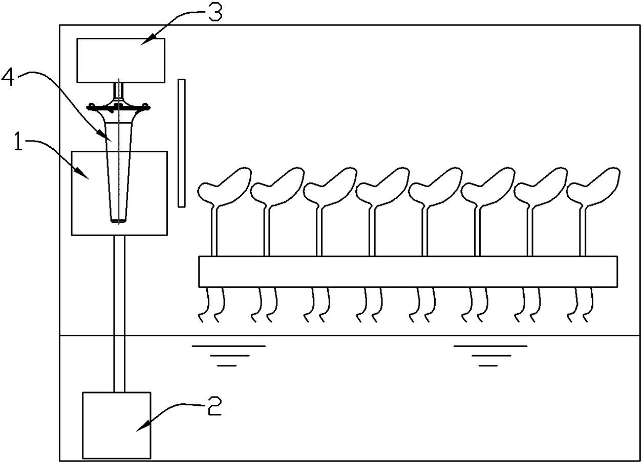
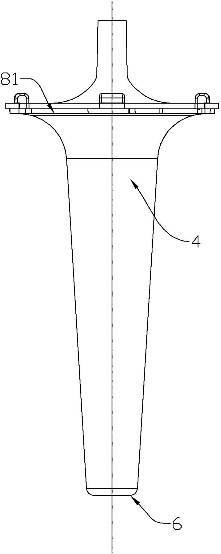
[0017] Example 1, such as figure 2 , The water pump 2 pumps water into the water-carrying platform 1, the cone of the cone 4 is downward and the bottom of the cone is upward, and the cone is inserted under the water surface of the water-carrying platform, and the motor 3 drives the cone to rotate. The cone 4 is provided with a water diversion cavity 5 on the shaft, and the bottom of the water diversion cavity communicates with the cone tip 6 of the cone. The cone tip 6 is provided with a blade 7 that can push water upward into the water diversion cavity 5 when rotating, such as Figure 7 , Picture 9 , There is a sprinkler hole 81 between the cone bottom and the side wall of the cone, and the upper part of the water diversion cavity communicates with the sprinkler hole 81, such as Figure 4 , When the cone rotates, the water in the water diversion cavity can be thrown out through the sprinkler hole.

[0018] When working, the water in the water-carrying container can flow up along...

Example Embodiment

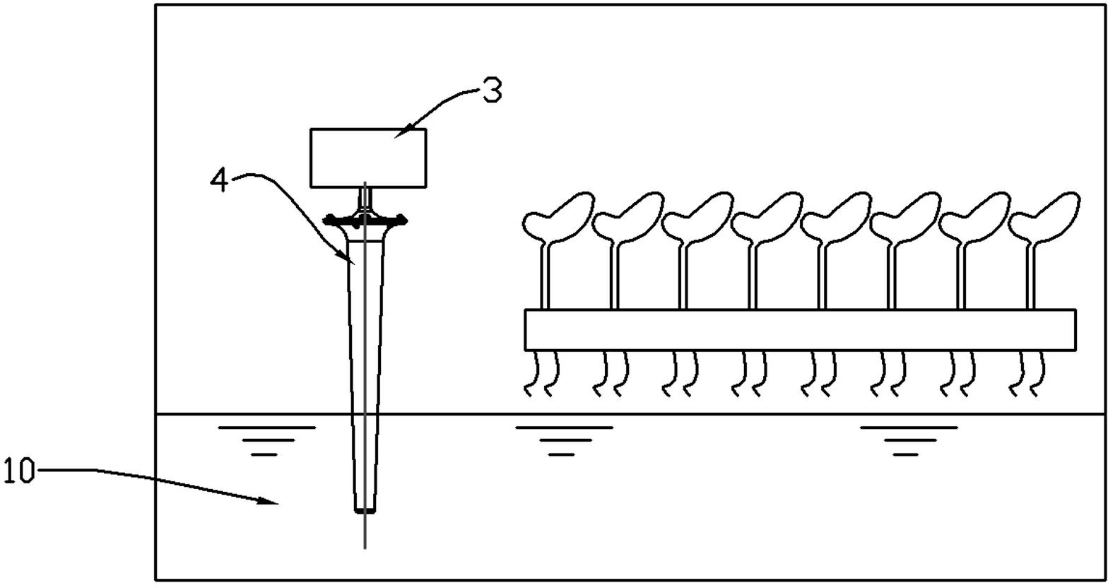
[0019] Example 2, such as image 3 The cone tip of the cone 4 is downward and the cone bottom is upward. The cone tip is directly inserted into the water-carrying container 10 and driven by the motor 3 to rotate. The cone 4 is provided with a water diversion cavity 5 on the shaft. The bottom of the water diversion cavity and the cone The cone tip part 6 is connected, and the cone tip part 6 is provided with a blade 7 that can push water upward into the water diversion cavity 5 when rotating, such as Figure 7 , Picture 9 , There is a sprinkler hole 81 between the cone bottom and the side wall of the cone, and the upper part of the water diversion cavity communicates with the sprinkler hole 81, such as Figure 4 , When the cone rotates, the water in the water diversion cavity can be thrown out through the sprinkler hole.

[0020] In the above embodiment, the cone 4 can also be provided with sprinkler holes 82 on the side wall near the bottom of the cone at the same time, communicat...


PUM


Abstract

The invention discloses a water sprinkling device of a plant cultivation machine. A water diversion cavity is arranged at the shaft part of a conical body and communicated with the cone tip of the conical body; a plurality of paddles capable of driving water up into the water diversion cavity during the rotation of the conical body are arranged at the cone tip; water sprinkling holes are arranged between the cone bottom and the sidewall of the conical body and/or on the sidewall close to the cone bottom; and the upper part of the water diversion cavity is communicated with the water sprinkling holes. When the water sprinkling device works, the attached water drops can be centrifugally drained by virtue of the surface of the conical body, and moreover, the water drops can be driven in the water diversion cavity by the paddles at the bottom of the water diversion cavity, ascended to the top of the water diversion cavity, and then are sprinkled outwards from the water sprinkling holes. The water-lifting height and water-lifting amount of the water sprinkling device are greatly increased, irrigation time every time the plant cultivation machine works is shortened, and energy consumption is lowered; and moreover, the sprinkled water drops can hardly be blocked by plants which grow tall, and water sprinkling is uniform.

Description

Technical field [0001] The invention relates to a sprinkler, particularly a sprinkler used in a plant cultivation machine. Background technique [0002] The Chinese patent with publication number "102487806A" discloses a sprinkler for plant cultivation machine, such as figure 1 , Which includes a water-carrying platform 1a, above the water-carrying platform there is a cone 4a with a rough surface, the cone is driven to rotate by the driving device 3a, the tip of the cone is inserted below the liquid surface of the water-carrying platform, and the bottom end of the cone is in the liquid Above the surface. When it rotates through the cone, the liquid can flow upwards along its surface to form a liquid film. When the conical liquid flows along the cone surface until the adhesion force with the cone surface cannot overcome the centrifugal force required for rotation, the liquid becomes tiny water particles , And fly out in a parabola along the tangent direction to complete the sprin...

Claims


Application Information

Patent Timeline
IPC IPC(8): A01G31/02
CPCY02P60/21
Inventor 钟太荣
Owner GUANGZHOU XINGRONG BIOLOGICAL TECH
Why Eureka
Try Eureka