Mold for punching needle bed insert blank used in computer knitting flat knitting machine

A flat knitting machine, inserting technology, applied in the direction of manufacturing tools, forming tools, metal processing equipment, etc., can solve the problems of large loss of thin steel strip material, easy deviation, scrap, etc., to ensure stamping quality, avoid interference, cost reduction effect

Inactive Publication Date: 2012-09-19
常熟市尚湖镇冶塘伟东模具厂
View PDF11 Cites 2 Cited by
  • Summary
  • Abstract
  • Description
  • Claims
  • Application Information

AI Technical Summary

Problems solved by technology

[0004] The existing technology mainly has the following technical problems in the process of punching the needle bed insert body by a punching machine (press machine): one, the efficiency is low, because due to The thin steel strip has both good elasticity and flexibility, so it is difficult to continuously introduce the punching machine for continuous punching (it is called continuous feeding and continuous punching in the industry), so the lengthy thin steel strip is usually cut to an appropriate length in advance, and then paid Various stamping forms, which not only increase the workload of the pre-processing work on the thin steel strip, but also affect the efficiency; second, the defect rate and / or scrap rate are high, because when the thin steel strip is introduced into the lower die mechanism due to the lack of guiding tube bundles And it is easy to deviate, and even the thin steel strip moves when the upper die touches the thin steel strip on the lower die, resulting in defective products or even scrapping; third, the material loss of the thin steel strip is large, resulting in high cost; , the thin steel strip that goes out of the mold after punching will have an impact on the working occasion
[0005] In view of the deficiencies in the above-mentioned prior art, the applicant has made an in-depth search of patent literature and non-patent literature, but none of them has found any technical inspiration that can be used for reference

Method used


Image

  • Mold for punching needle bed insert blank used in computer knitting flat knitting machine
  • Mold for punching needle bed insert blank used in computer knitting flat knitting machine
  • Mold for punching needle bed insert blank used in computer knitting flat knitting machine

Examples


Embodiment Construction

[0014] In order to enable the examiners of the patent office, especially the public, to understand the technical essence and beneficial effects of the present invention more clearly, the applicant will describe in detail the following in the form of examples, but none of the descriptions to the examples is an explanation of the solutions of the present invention. Any equivalent transformation made according to the concept of the present invention which is merely formal but not substantive shall be regarded as the scope of the technical solution of the present invention.

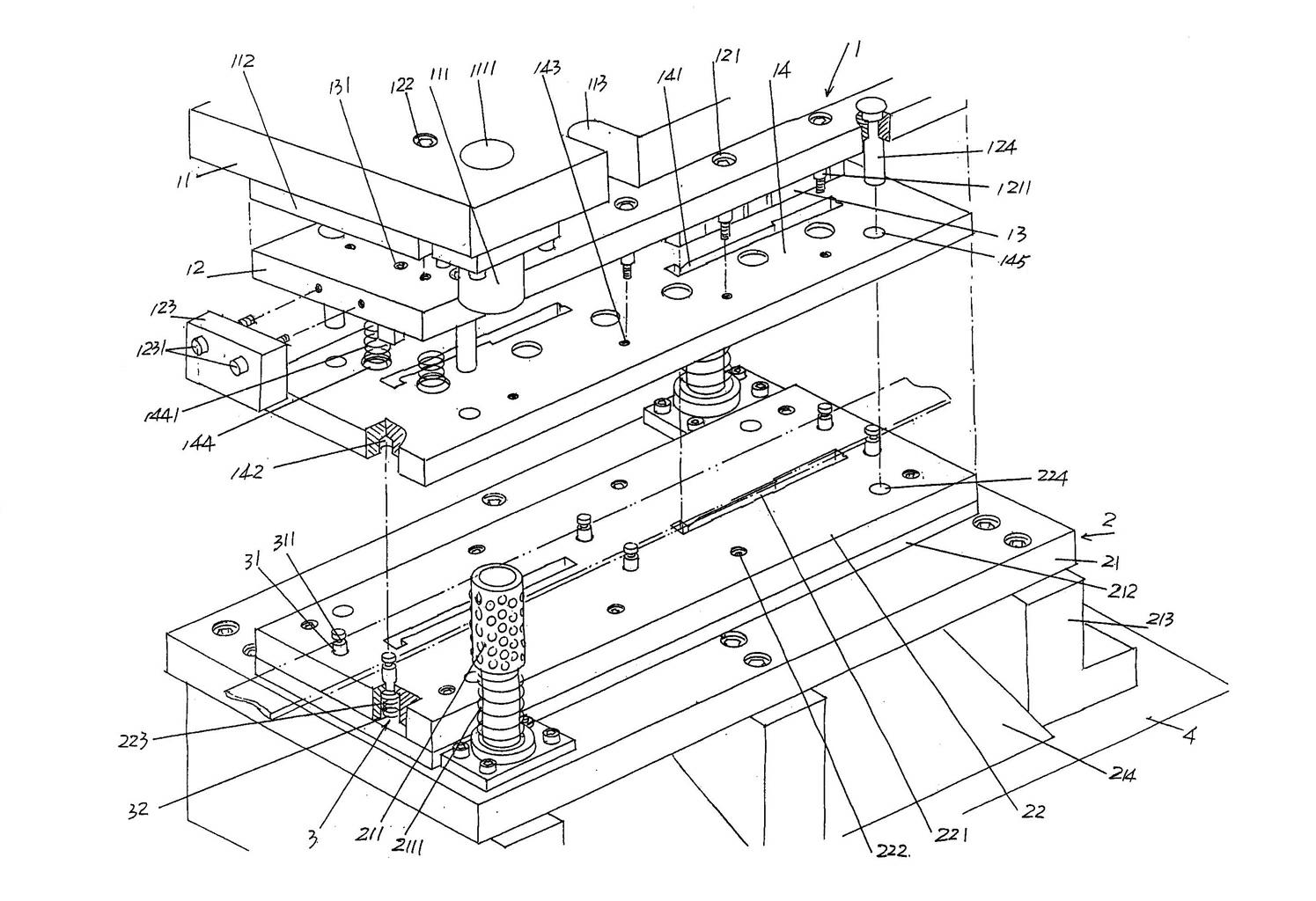
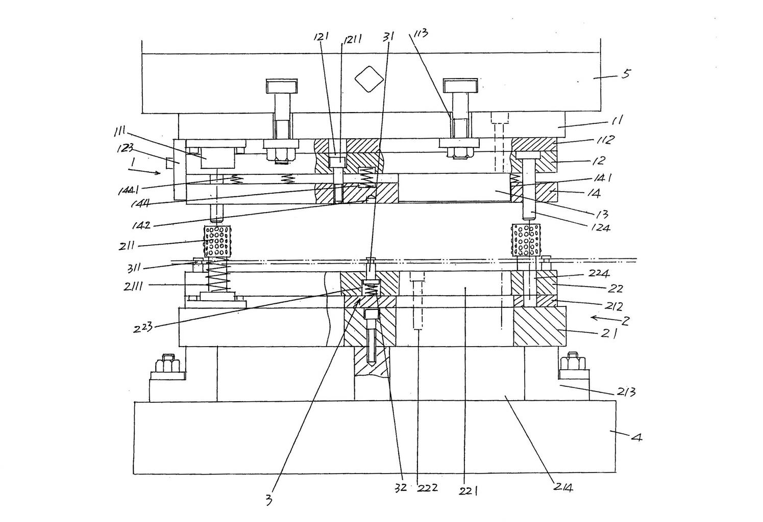
[0015] Please see figure 1 with figure 2 , in order to facilitate public understanding, the applicant in figure 1 The base platform 4 of the punching machine is shown in the figure, the base platform 4 can also be called the working platform, and in figure 2 Shown in the stamping machine is the upper die frame fixing seat 5 of the punching machine. The upper mold mechanism 1 is fixed on the uppe...


PUM


Abstract

The invention discloses a mold for punching a needle bed insert blank used in a computer knitting flat knitting machine, belonging to the technical field of molds; the mold comprises an upper mold mechanism and a lower mold mechanism; the upper mold mechanism comprises an upper template holder, an upper template and an insert male punching mold; the lower mold mechanism comprises a lower template holder and a lower template; the mold is characterized in that the upper mold mechanism further comprises a material press plate connected with one side of the upper template; a mold guide hole is arranged on the material press plate; one side of the lower template, and two sides of a mold cavity corresponding to tool edges are provided with a group of thin steel strip guiding and limiting mechanisms for guiding and limiting the thin steel strips, respectively; each thin steel strip guiding and limiting mechanism is matched with the material press plate; a material cutter is fixed on the upper template; and the material cutter corresponds to the left end of the mold guide hole. The mold has the advantages that the mold is helpful to realize the continuous punching, so as to enhance the efficiency and satisfy the industrialization amplification production requirements; the thin steel strip is prevented from offset or up-warping, so that the punching quality is ensued, the fault is avoided so as to save materials and reduce cost; and the operation field is protected from interference.

Description

technical field [0001] The invention belongs to the technical field of moulds, and in particular relates to a mold for punching a needle bed blank for a computerized flat knitting machine. Background technique [0002] As known to manufacturers of computerized flat knitting machines and manufacturers using computerized flat knitting machines to produce fabrics, the knitting needles of the knitting mechanism of the flat knitting machine extend out of the needle grooves of the needle bed when transferring and receiving needles. The distance is much longer than the distance extending out of the needle bed during normal knitting, so a needle bed insert is required on the needle bed, and the needle bed insert can protect the knitting needles and prevent the knitting needles from performing operations such as transfer and stitching. During the stitching process, tampering and / or deflection occur due to protruding from the needle bed, and finally avoid broken needles and missed sti...

Claims


Application Information

Patent Timeline
Patent Type & Authority Applications(China)
IPC IPC(8): B21D37/10B21D43/00
Inventor 姚卫东顾建忠
Owner 常熟市尚湖镇冶塘伟东模具厂
Why Eureka
Try Eureka