Bidirectional flexible fixture

A technology of flexible fixtures and fixtures, applied in the direction of clamping, manufacturing tools, supports, etc., can solve the problem that the fixture is difficult to clamp the workpiece, and achieve the effect of easier clamping

Active Publication Date: 2012-09-19
兰溪瑞鼎机床股份有限公司
View PDF8 Cites 0 Cited by
  • Summary
  • Abstract
  • Description
  • Claims
  • Application Information

AI Technical Summary

Problems solved by technology

[0002] When the machine tool processes irregular and complex workpieces, it is often difficult for the fixture to clamp the workpiece

Method used


Image

  • Bidirectional flexible fixture
  • Bidirectional flexible fixture
  • Bidirectional flexible fixture

Examples


Embodiment Construction

[0008] The following examples are only used to illustrate the technical solutions of the present invention.

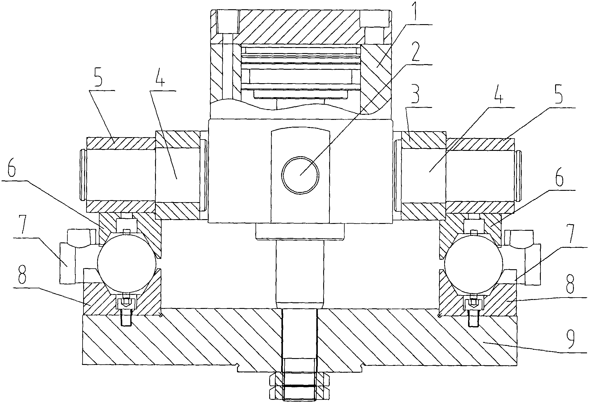
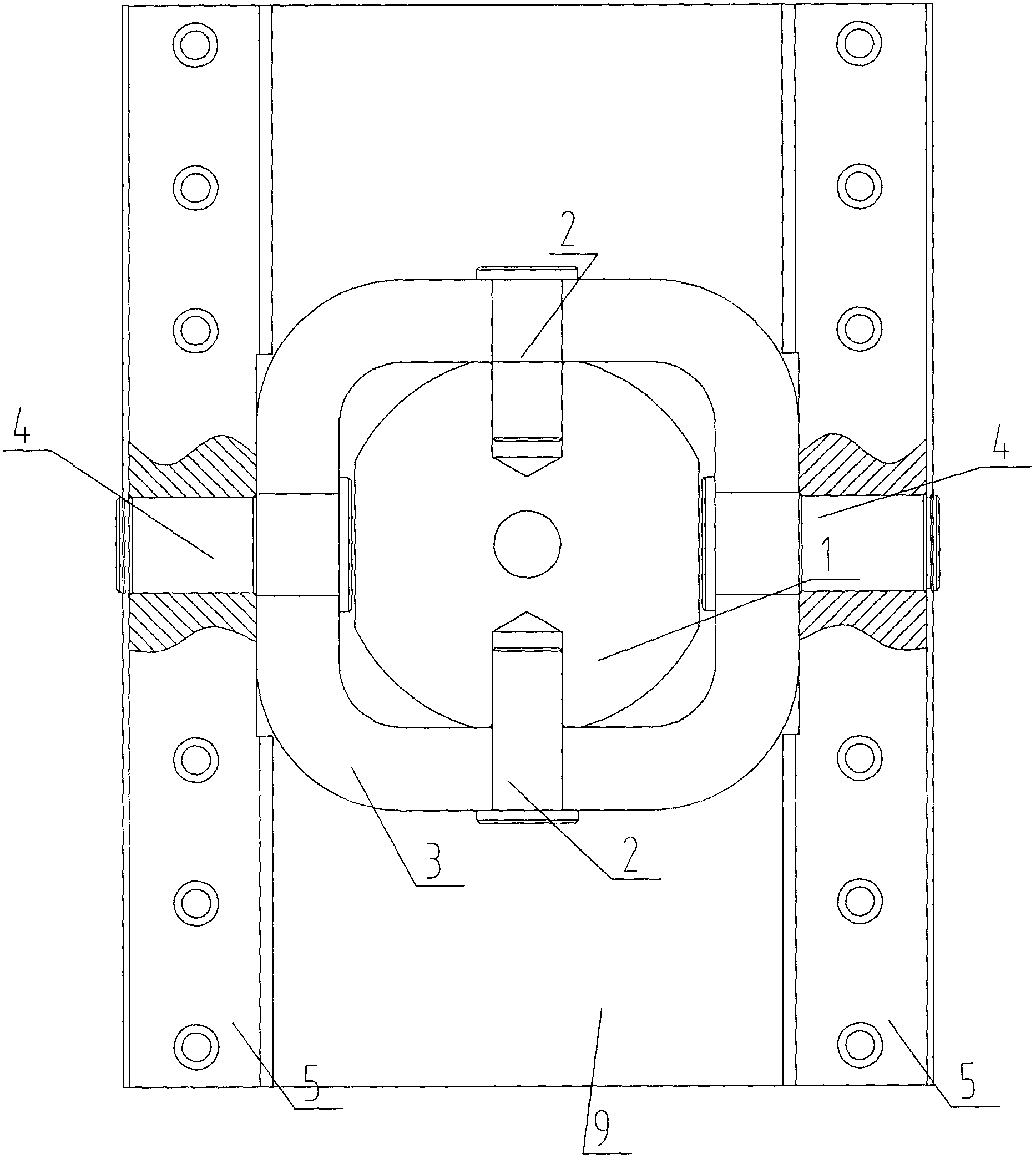
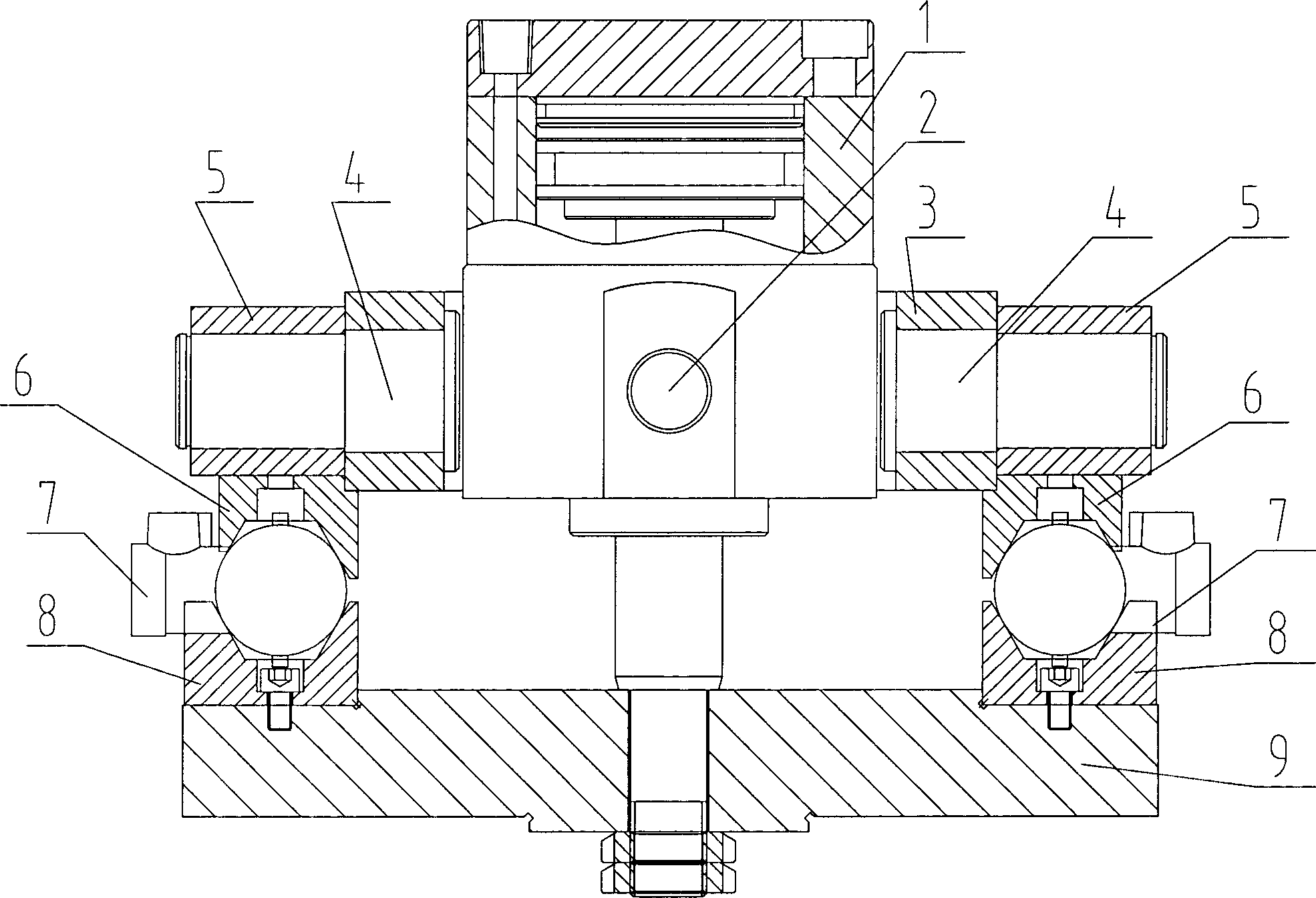
[0009] The two-way flexible fixture is characterized in that it includes an oil cylinder 1, a vertical pin 2, a swing ring 3, a horizontal pin 4, an upper fixture seat 5, an upper fixture 6, a lower fixture 8, and a bottom plate 9. The oil cylinder 1 is equipped with a swing ring 3, The upper fixture seat 5 is installed on the outer two opposite sides of the swing ring 3, the vertical pin 2 makes the oil cylinder 1 and the swing ring 3 become movably connected, the horizontal pin 4 makes the swing ring 3 and the upper fixture seat 5 become movably connected; the upper fixture seat 5 An upper clamp 6 is fixedly installed, and a lower clamp 8 is installed under the upper clamp 6, and the lower clamp 8 is fixedly mounted on the bottom plate 9 below it. During work, the workpiece 7 is installed between the upper clamp 6 and the lower clamp 8, and the lifting cylinder 1 can...


PUM


Abstract

The invention discloses a bidirectional flexible fixture which is characterized by comprising an oil cylinder (1), a vertical pin (2), a swinging ring (3), horizontal pins (4), upper fixture seats (5), upper fixtures (6), lower fixtures (8) and a base plate (9); the swinging ring (3) is installed outside the oil cylinder (1); the upper fixture seats (5) are installed at two opposite surfaces out of the swinging ring (3);the oil cylinder (1) and the swinging ring (3) are in movable connection by the vertical pin (2); the swinging ring (3) and the upper fixture seats (5) are in movable connection through the horizontal pins (4); the upper fixtures (6) are fixedly installed below the upper fixture seats (5); the lower fixtures (8) are installed below the upper fixtures (6); and the lower fixtures (8) are fixedly installed on the base plate (9) below the lower fixtures (8). Complex workpieces can be clamped easily by the bidirectional flexible fixture provided by the invention.

Description

technical field [0001] The present invention relates to bi-directional flexible clamps. Background technique [0002] When machine tools process irregular and complex workpieces, it is often difficult for fixtures to clamp the workpiece. Contents of the invention [0003] The technical problem to be solved by the invention is to provide a bidirectional flexible clamp that can more easily clamp complex workpieces. [0004] The technical solution created by the present invention: a two-way flexible clamp is characterized in that it includes an oil cylinder, a vertical pin, a swing ring, a horizontal pin, an upper clamp seat, an upper clamp, a lower clamp, and a bottom plate. The upper fixture seat is installed on the opposite side of the outer two. The vertical pin makes the oil cylinder and the swing ring into a movable connection, and the horizontal pin makes the swing ring and the upper fixture seat into a movable connection; The lower fixture is fixed on the bottom pla...

Claims


Application Information

Patent Timeline
Patent Type & Authority Applications(China)
IPC IPC(8): B23Q3/00
Inventor 郑伟民
Owner 兰溪瑞鼎机床股份有限公司
Why Eureka
Try Eureka