

Hydraulic clamping device for electromechanical equipment
A kind of electromechanical equipment, hydraulic clamping technology, applied in mechanical equipment, supporting machine, machine/stand and other directions, can solve the problems of easily damaged fixing seat, damaged electromechanical equipment, poor clamping effect, etc., to achieve convenient clamping , to ensure the effect of the installation effect
- Summary
- Abstract
- Description
- Claims
- Application Information
AI Technical Summary
Problems solved by technology
Method used
Image

Examples
Embodiment 1
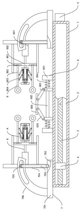
[0022] Example 1: Please refer to Figure 1-3 , in an embodiment of the present invention, a hydraulic clamping device for electromechanical equipment, including a base 1, also includes:
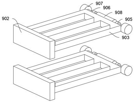
[0023] An adjusting mechanism 7 is slidably arranged on the base 1, and a fastening mechanism 8 is arranged on the adjusting mechanism 7, and an auxiliary fixing mechanism 9 is arranged on the fastening mechanism 8, and the adjusting mechanism 7 is used for adjusting the clamping of the fastening mechanism 8. The angle is convenient for the clamping of different types of electromechanical equipment, and the auxiliary fixing mechanism 9 is used to pre-fix the electromechanical equipment, so as to facilitate the fixing of the electromechanical equipment by the fastening mechanism 8;
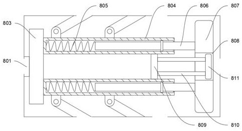
[0024] The fastening mechanism 8 includes a fixed frame 802 and a telescopic member 801 arranged on the adjustment mechanism 7, the telescopic end of the telescopic member 801 is slidably connected to the fixed f...
Embodiment 2
[0032] Embodiment 2: This embodiment is a further improvement on the previous embodiment: please refer to figure 1 In one case of the embodiment, the adjustment mechanism 7 includes a support plate 701 arranged on the slider 4, and a groove 702 is provided near one end of the two support plates 701, and a rotating plate 704 is arranged in the groove 702 for rotation, The outer side of the groove 702 is rotatably equipped with a driving rod 703, and the end of the driving rod 703 away from the center of rotation is rotatably connected to the rotating plate 704 through a sliding post 705. The sliding column 705 slides in the arc-shaped groove block 706 .
[0033] see figure 1 , in one case of the embodiment, the fixed frame 802 and the telescopic member 801 are arranged on the rotating plate 704 .
[0034]In this embodiment, specifically, when the driving rod 703 is rotated, the sliding column 705 connected to the end of the driving rod 703 away from the rotation center slides...
PUM
 Abstract
Description
Claims
Application Information