Oil exploitation device

A technology for oil extraction and fixing plates, which is applied in the fields of fluid extraction, earth-moving drilling, wellbore/well components, etc. It can solve the problems of high protection and danger, avoid potential safety hazards, avoid injury accidents, and ensure installation. Effect

Inactive Publication Date: 2020-11-20
魏洪
View PDF1 Cites 3 Cited by
  • Summary
  • Abstract
  • Description
  • Claims
  • Application Information

AI Technical Summary

Problems solved by technology

[0003] China Publicly Authorized Invention: Intelligent Oil Exploitation Pump (public number: CN107605437A) discloses an intelligent oil extraction pump, which can be connected to the controller so that the device can be controlled by the valve controller of the pulling device when it is in use. The vent pipe is used to control the ventilation of the pumping body, and the pumping motor drives the pump impeller inside the pumping body to exhaust or inflate the pumping chamber and the rubber threaded pipe, so that the rubber threaded pipe can be compressed or raised, and then through the pumping The connecting rod drives the main transmission arm to go up and down, so that the main transmission arm can drive the extraction pump rod locked by the pull rope assembler to perform oil pumping operation. For the convenience of maintenance or installation on the platform, the existing pumping unit is installed on the platform. There is a ladder on the outside of the pumping unit frame, and then only the position where the ladder is located and the nearby positions can be inspected during maintenance. The danger is high, and the ladder can only be used for maintenance, and the driving mechanism of the oil production device is exposed outside. , it cannot be protected, therefore, an oil extraction device is proposed

Method used


Image

  • Oil exploitation device
  • Oil exploitation device
  • Oil exploitation device

Examples


Embodiment

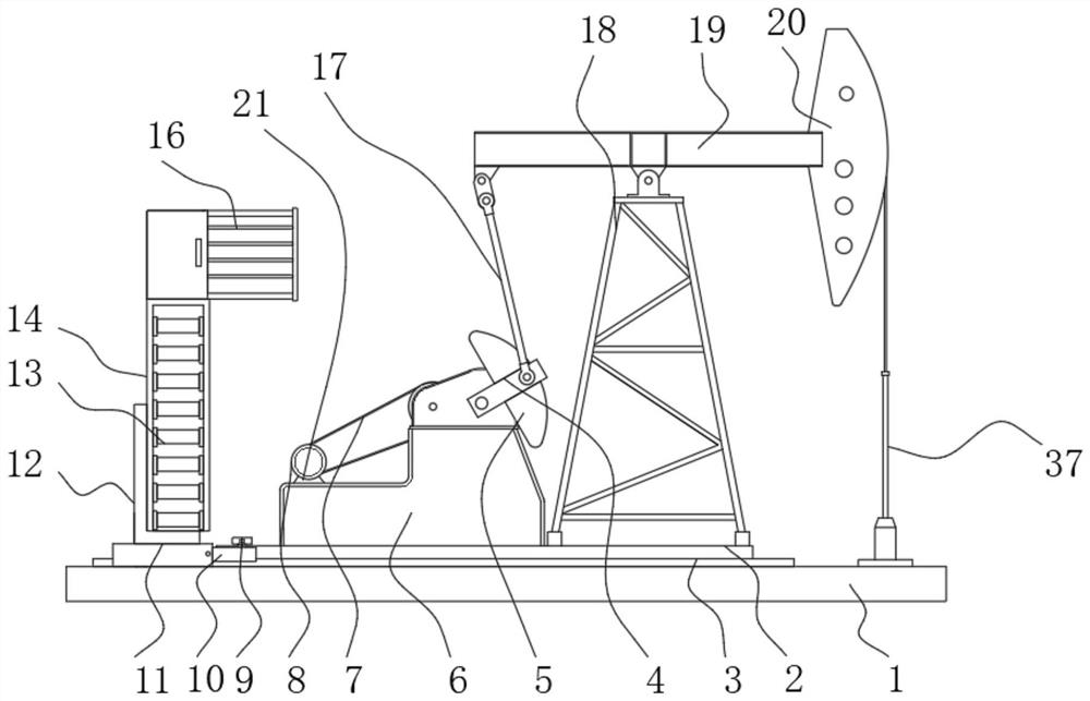
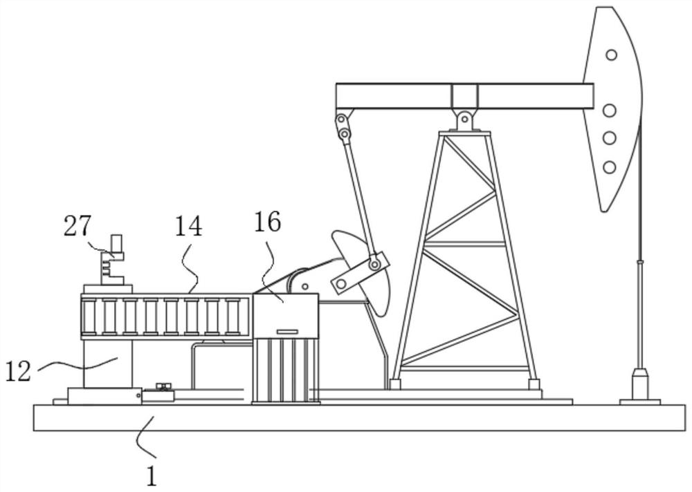
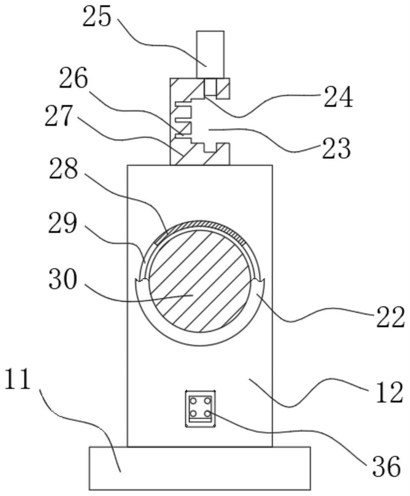
[0025] see Figure 1-6 , the present invention provides a technical solution: an oil extraction device, comprising a base 1, the top of the base 1 is welded with a fixed plate 2, one side of the fixed plate 2 is fixedly connected with a bracket 18, and the top of the bracket 18 is hinged with a beam 19 One side of the beam 19 is fixedly connected with a donkey head 20, the inside of the donkey head 20 is provided with a sucker rod 37, the side of the beam 19 away from the donkey head 20 is hinged with a connecting rod 17, and one end of the connecting rod 17 is hinged with a crank 4. The top side of the fixed plate 2 is fixedly connected with the reduction box 6, the output end of the reduction box 6 is fixedly connected with the crank 4, the side of the crank 4 is welded with the balance weight 5, and the top of the base 1 is fixedly connected with a U-shaped The slide rail 3, the outer wall of the U-shaped slide rail 3 is slidingly connected with two first sliders 11, the to...


PUM


Abstract

The invention discloses an oil exploitation device. The oil exploitation device is characterized in that a fixing plate is welded to the top of a base, a support is fixedly connected with one side ofthe fixing plate, a walking beam is hinged to the top of the support, a horsehead is fixedly connected with one side of the walking beam, a sucker rod is arranged inside the horsehead, and a connecting rod is hinged to the side, away from the horsehead, of the walking beam; a crank is hinged to one end of the connecting rod, so that one side of an overhaul platform is attached to the top of the base, a support is formed between the overhaul platform and the first shell, and the two sides of the oil extraction device are effectively protected among a frame body, stair steps and the overhaul platform in the transverse direction; and the frame body is moved towards the crank, the accident that people are hurt by the rotating part of the crank is avoided, and the oil extraction safety is ensured. Through cooperation of first sliding blocks, U-shaped sliding rails, the frame body, the stair steps and the overhaul platform, the overhaul platform is moved to the position needing to be overhauled or repaired, and through the overhaul platform, potential safety hazards existing in workers during maintenance are avoided.

Description

technical field [0001] The invention relates to the technical field of oil extraction, in particular to an oil extraction device. Background technique [0002] Oil is a fluid mineral buried deep in the ground. At first, people called the oily liquid minerals produced in nature petroleum, the combustible gas natural gas, and the solid combustible fuel minerals bitumen. With the in-depth study of these minerals, it is realized that they are all hydrocarbon compounds in composition and are related to each other in origin, so they are collectively called petroleum. Oil extraction refers to the act of digging and extracting oil in places where oil is stored. In the process of oil extraction, oil and gas flow from the reservoir to the bottom of the well, and then rise from the bottom of the well to the wellhead; [0003] China Publicly Authorized Invention: Intelligent Oil Exploitation Pump (public number: CN107605437A) discloses an intelligent oil extraction pump, which can be...

Claims


Application Information

Patent Timeline
Patent Type & Authority Applications(China)
IPC IPC(8): E21B43/00E21B41/00
CPCE21B41/00E21B43/127
Inventor 魏洪
Owner 魏洪
Why Eureka
Try Eureka