
Automatic assembly device for clamping spring

A technology of automatic assembly device and power device, which is applied in metal processing, metal processing equipment, manufacturing tools, etc., can solve the problems of difficult and time-consuming circlips, and achieve the effect of ensuring detection.

Active Publication Date: 2020-01-03
卓越(昆山)自动化技术有限公司
View PDF7 Cites 3 Cited by
  • Summary
  • Abstract
  • Description
  • Claims
  • Application Information

AI Technical Summary

Problems solved by technology

[0003] The purpose of the present invention is to provide an automatic assembling device for circlips, so as to solve the shortcomings of the difficulty and time-consuming manual installation of circlips in the prior art

Method used


Image

  • Automatic assembly device for clamping spring
  • Automatic assembly device for clamping spring
  • Automatic assembly device for clamping spring

Examples


Embodiment Construction

[0028] In order to make the technical means, creative features, goals and effects achieved by the present invention easy to understand, the present invention will be further described below in conjunction with specific embodiments.

[0029] It should be noted that, in the description of the present invention, the terms "front", "rear", "left", "right", "upper", "lower", "inner", "outer" and the like indicate orientations or positions The relationship is based on the orientation or positional relationship shown in the drawings, and is only for the convenience of describing the present invention and does not require that the present invention must be constructed and operated in a specific orientation, and thus should not be construed as a limitation of the present invention. The terms "front", "rear", "left", "right", "upper" and "lower" used in the description of the present invention refer to the directions in the drawings, and the terms "inner" and "outer" refer to is the dir...


PUM


Abstract

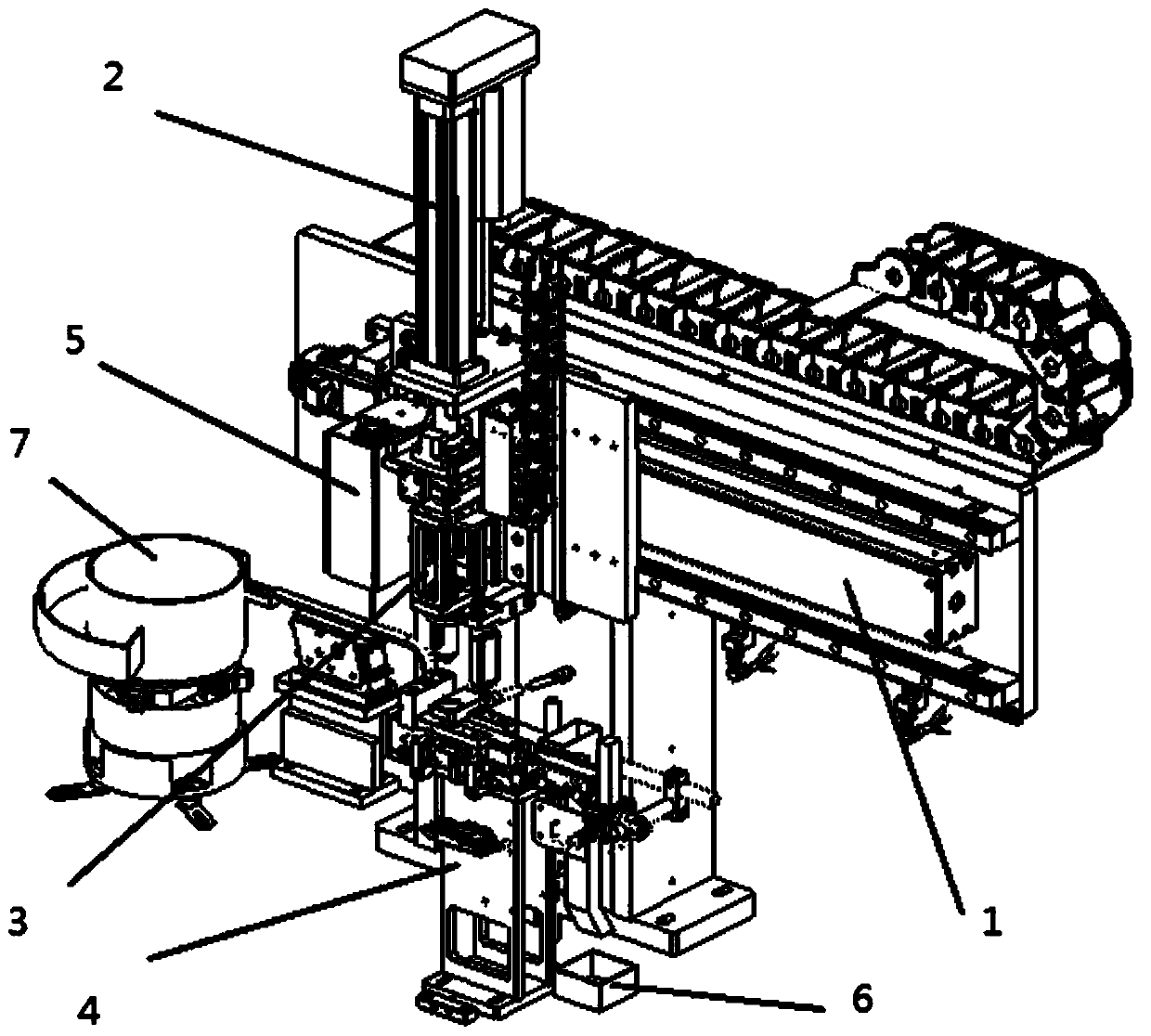
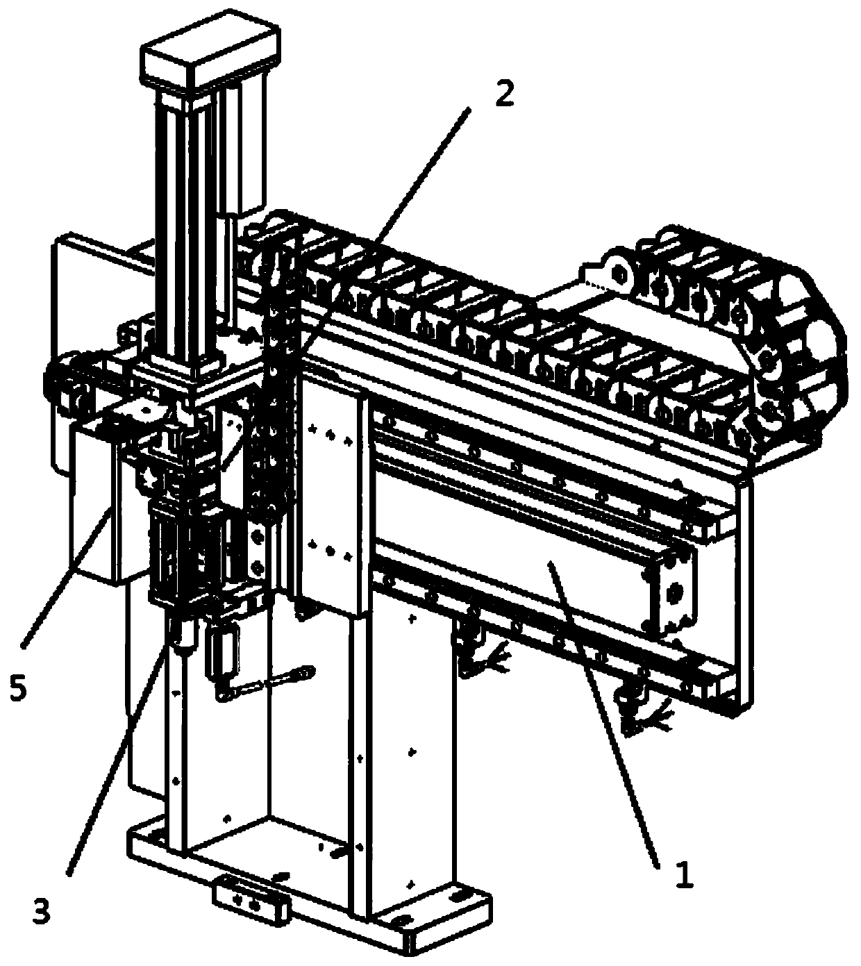
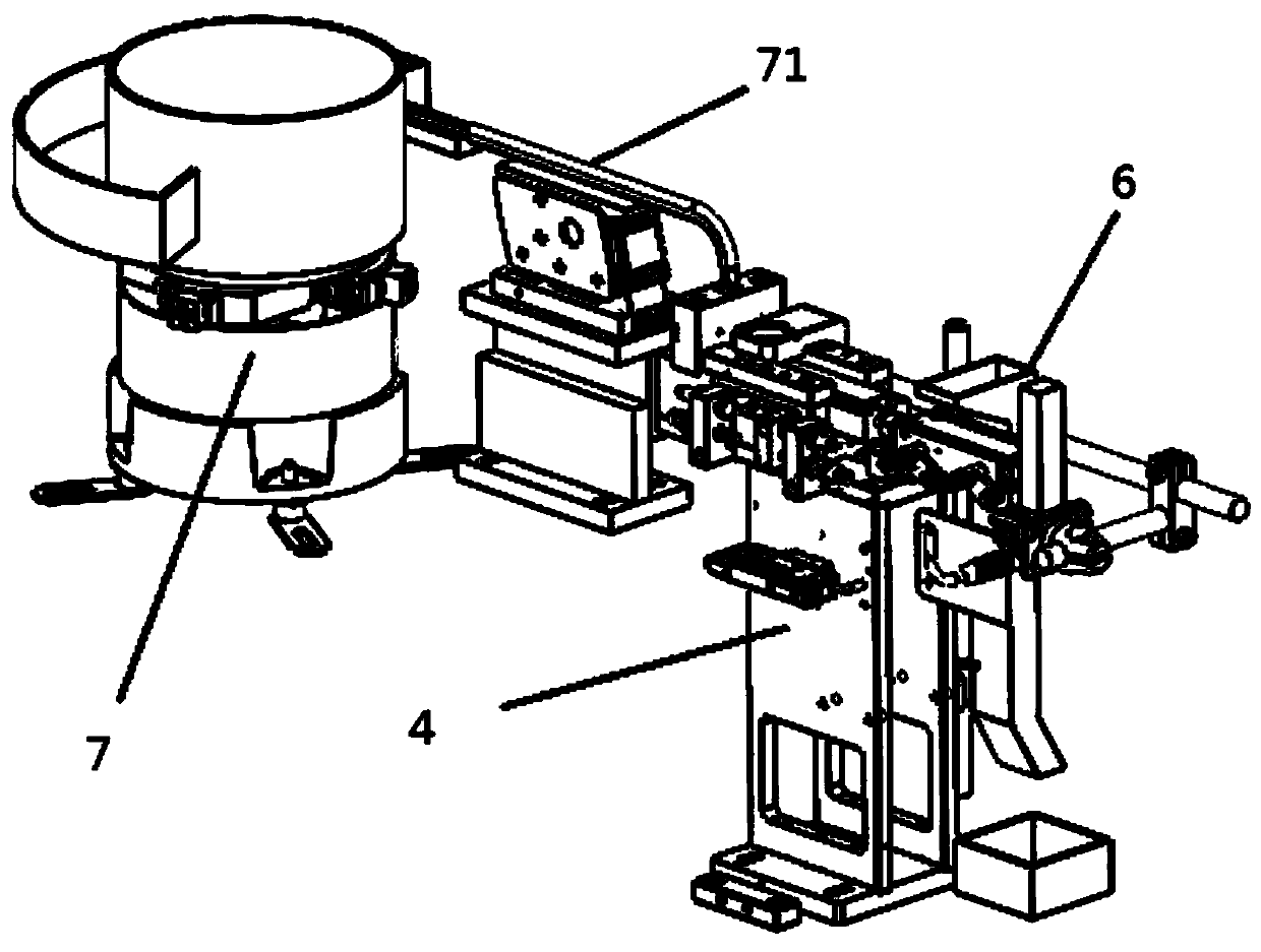
The invention discloses an automatic assembly device for a clamping spring. The automatic assembly device for the clamping spring comprises an X-axis moving module, a Z-axis moving module and a material taking module, the Z-axis moving module is connected to the X-axis moving module, and the material taking module is connected to the Z-axis moving module; the material taking module includes a power unit, a material taking shaft and a guide sleeve, the material taking shaft is connected to the output end of the power unit, the guide sleeve is connected with the power unit, and the power unit works to drive the material taking shaft to extend and retract in the guide sleeve; and the X-axis moving module and the Z-axis moving module move to drive the material taking module to move to a material taking position, the material taking shaft is extended to take the clamping spring, and the X-axis moving module and the Z-axis moving module move, so that the material taking module moves to a mounting position, the material taking shaft retracts, and the Z-axis moving module is descended to mount the clamping spring. According to the automatic assembly device for the clamping spring, materialtaking can be quickly performed, during mounting, the clamping spring is mounted by the combined action of the retracting of the material taking shaft and the descending of the Z-axis moving module,the mounting effect of the clamping spring is ensured, and the efficiency is improved.

Description

technical field [0001] The invention relates to the technical field of circlip installation, in particular to an automatic assembling device for circlips. Background technique [0002] Circlips are also called retaining rings or clasps, which are a type of fasteners. They are installed in the shaft grooves or hole grooves of machines and equipment to prevent the axial movement of parts on the shaft or holes. The existing circlips and shafts are basically assembled manually. Manual assembling of the circlips has the following disadvantages: high difficulty, long time consumption, and easy damage of the circlips. Contents of the invention [0003] The object of the present invention is to provide an automatic assembling device for a circlip, so as to solve the disadvantages of difficulty and time-consuming manual assembling of the circlip in the prior art. [0004] In order to achieve the above object, the present invention is achieved by adopting the following technical so...

Claims


Application Information

Patent Timeline
Patent Type & Authority Applications(China)
IPC IPC(8): B23P19/00B23P19/04B23P19/08
CPCB23P19/00B23P19/001B23P19/04B23P19/08
Inventor 程乐
Owner 卓越(昆山)自动化技术有限公司
Learn More