Manufacturing die of unmanned aerial vehicle blade

A technology of drones and blades, which is applied to household appliances, other household appliances, household components, etc., can solve the problem that it is difficult to ensure the consistency of the installation angle between the blade body and the positioning pin, and it is difficult to ensure the balance and safety of high-speed rotating blades. , angular positioning deviation and other problems, to achieve the effect of low scrap rate, low manufacturing cost and high deflection angle accuracy

Pending Publication Date: 2020-06-05
AVIC HUIYANG AVIATION PROPELLER
View PDF0 Cites 3 Cited by
  • Summary
  • Abstract
  • Description
  • Claims
  • Application Information

AI Technical Summary

Problems solved by technology

The positioning pin is mechanically formed with the positioning sleeve, and the forming process is complicated
The leaf body of the blade is integrated with the petiole when the mold is formed; when the mold is formed, the positioning of the blade is processed by machining, and the angular positioning deviation is large. On the other hand, it is not easy to ensure the consistency of the installation angle between the blade body and the positioning pin, which leads to the poor consistency of the angle between the blade positioning pin and the blade body, and it is difficult to ensure the balance and safety of the high-speed rotating blade

Method used


Image

  • Manufacturing die of unmanned aerial vehicle blade
  • Manufacturing die of unmanned aerial vehicle blade
  • Manufacturing die of unmanned aerial vehicle blade

Examples


Embodiment Construction

[0031] The present invention will be further described below in conjunction with the accompanying drawings and specific embodiments.

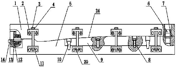
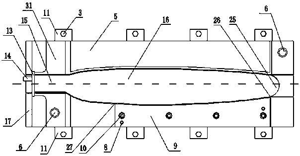
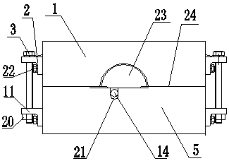
[0032] Such as Figure 1 to Figure 19As shown, this embodiment includes an upper mold 1, a lower mold and positioning pins I6. The mold cavity that completely matches the blade airfoil 16 is divided into an upper mold 1 and a lower mold on the curved surface formed by the line connecting the front and rear edge maximum contour lines 24 of the blade airfoil 16, and the mold cavity is divided into an upper mold cavity 28 and a lower mold cavity 30. The upper mold 1 and the lower mold are provided with semicircular receiving grooves 35 and 33 of the petiole 15 on the end wall at one end of the petiole 15, that is, on the left walls 29 and 31 of the upper and lower die cavities. The lower mold is on the lower mold cavity end wall corresponding to the blade trailing edge, that is, the lower mold cavity front wall 36, and cuts out the cutting block...


PUM


Abstract

The invention discloses a manufacturing die of an unmanned aerial vehicle blade. The manufacturing die comprises an upper die, a lower die and positioning pins I; the lower die cuts cutting blocks rightwards from the left reflex angle zero-degree line position on the front wall of a lower die cavity corresponding to the trailing edge of the blade, the right end face of each cutting block corresponds to the starting position of the arc transition of the tail end of a blade body and the tail end of a blade tip, the lower end face of each cutting block is lower than the lowest point of the intersection line of the front wall of the lower die cavity and the bottom face of the lower die cavity, the rear end face of each cutting block are the inner end face of the front wall of the lower die cavity, and the front end face of each cutting block is not larger than the outer end face of the front wall of the lower die cavity; the symmetrical positioning pins I are arranged at the left end and the right end of the upper end face of a lower die block, positioning holes I are formed in the lower end face of the upper die, and after die is closed, the positioning pins I are located in the positioning holes I correspondingly; fixing mechanisms are evenly arranged on the front walls and the rear walls of the upper die block and the lower die block, and after die is closed, the upper die blockand the lower die block are fixed together through the fixing mechanisms. The manufacturing die is easy to manufacture, low in manufacturing cost, high in manufacturing precision and low in rejectionrate; and the unmanned aerial vehicle blade manufactured by the manufactured die is easy to demold, low in manufacturing cost and high in blade quality.

Description

technical field [0001] The invention belongs to the technical field of making drone blades, and relates to a mold for making drone blades. Background technique [0002] UAV is an emerging industry, which is widely used in military and civilian fields. The blades of the UAV are the main moving parts to meet the power of the UAV. With the development of my country's aviation industry, drones have become one of the new development industries of the aviation industry. [0003] Generally, the blade is made by a mould. The blade mold is generally separated on the curved surface formed by the line connecting the largest contour line of the front and rear edges of the blade body. According to the placement position, it is divided into an upper mold and a lower mold. Due to the requirements of high performance and fast speed of the UAV, the blade is a sheet structure, and the length of the blade is small, generally about 1-3 meters, so the twist angle of the blade body is relativel...

Claims


Application Information

Patent Timeline
Patent Type & Authority Applications(China)
IPC IPC(8): B29C33/44B29L31/08
CPCB29C33/44B29L2031/082
Inventor 凌磊寇巧娜李伯瀚孙晓岩
Owner AVIC HUIYANG AVIATION PROPELLER
Why Eureka
Try Eureka