
Mechanical safety mechanism of injection molding machine

A mechanical insurance and injection molding machine technology, applied in the field of injection molding machines, can solve the problems of easy wear of pull rivets, lack of mechanical insurance, and inability to effectively guarantee the personal safety of injection molding machine operators, so as to achieve good safety and avoid personal injury Effect

Inactive Publication Date: 2012-09-19
NINGBO HAIRI PLASTIC MACHINERY
View PDF4 Cites 4 Cited by
  • Summary
  • Abstract
  • Description
  • Claims
  • Application Information

AI Technical Summary

Problems solved by technology

[0002] In order to ensure the safety of the injection molding machine, the injection molding machine is equipped with a safety door. After the safety door is opened, the injection molding machine cannot perform mold closing action to realize shutdown protection. In this way, a mechanical safety structure needs to be added to avoid danger. The existing injection molding After the safety door is closed, the mechanical safety mechanism mainly uses the pull stud installed on the guide rail, and uses the raised part of the pull stud to block the door wheel, so as to realize the mechanical insurance. Patent Document [Notice No.: CN201506021] discloses an anti-retraction device for safety doors of injection molding machines, including cup head screws, springs, a first anti-retraction main body and a second anti-retraction main body. The main body and the second anti-retraction main body clamp the anti-retraction rod of the door wheel shaft to achieve mechanical insurance. It can be seen that the structure simply relies on the force of the spring to achieve mechanical insurance. With long-term use, the elastic force will weaken. , so that it will not play the role of mechanical insurance, and cannot effectively guarantee the personal safety of injection molding machine operators

Method used


Image

  • Mechanical safety mechanism of injection molding machine
  • Mechanical safety mechanism of injection molding machine
  • Mechanical safety mechanism of injection molding machine

Examples


Embodiment Construction

[0016] The following are specific embodiments of the present invention and in conjunction with the accompanying drawings, the technical solutions of the present invention are further described, but the present invention is not limited to these embodiments.

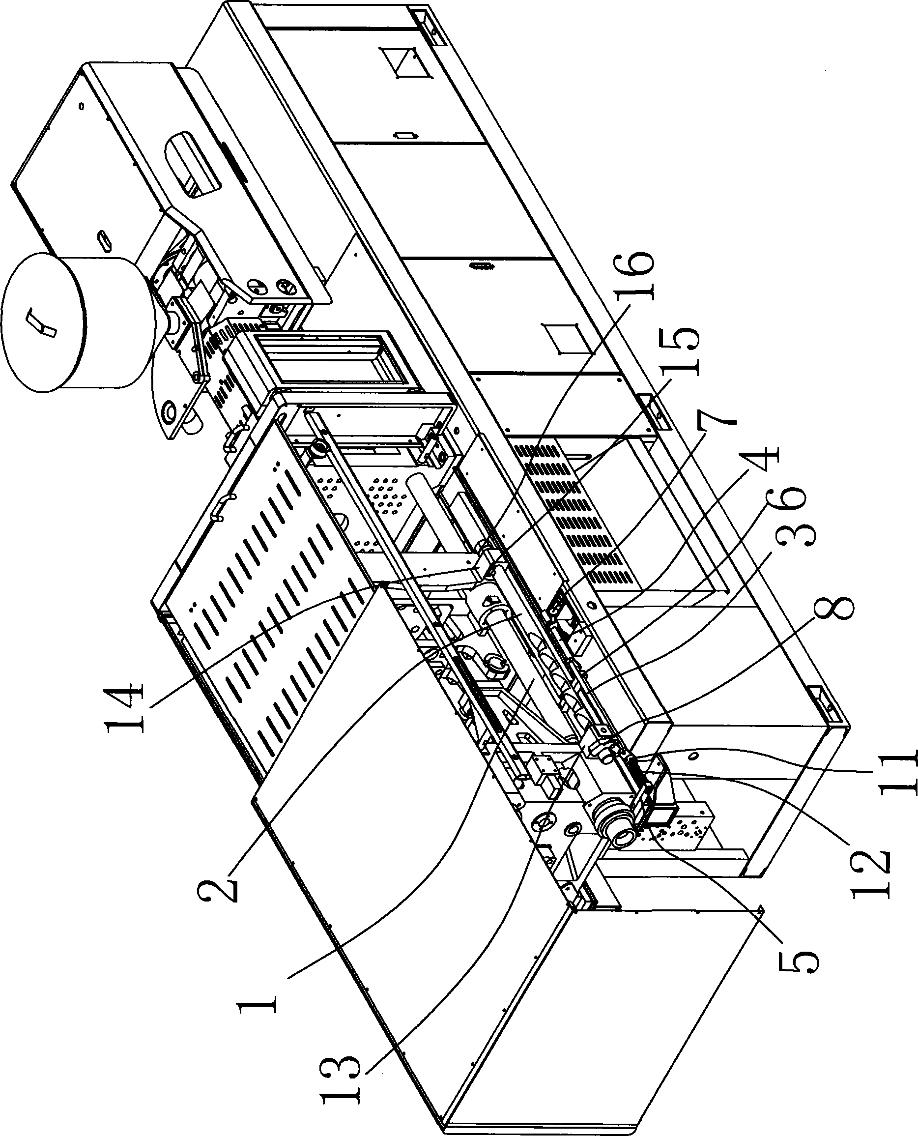
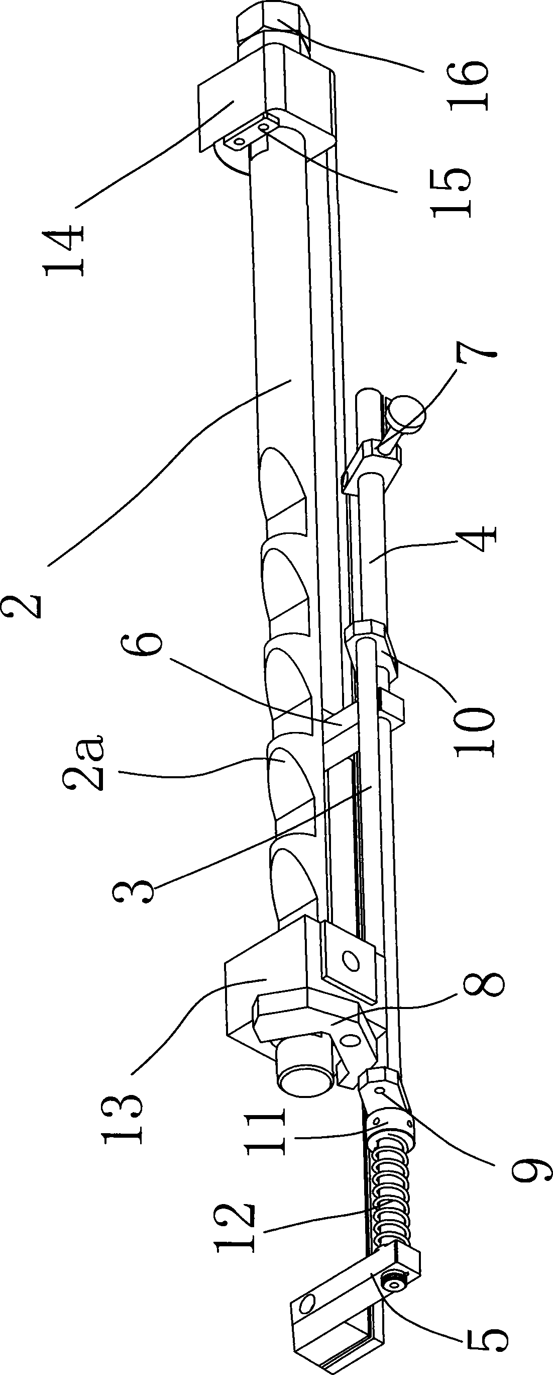
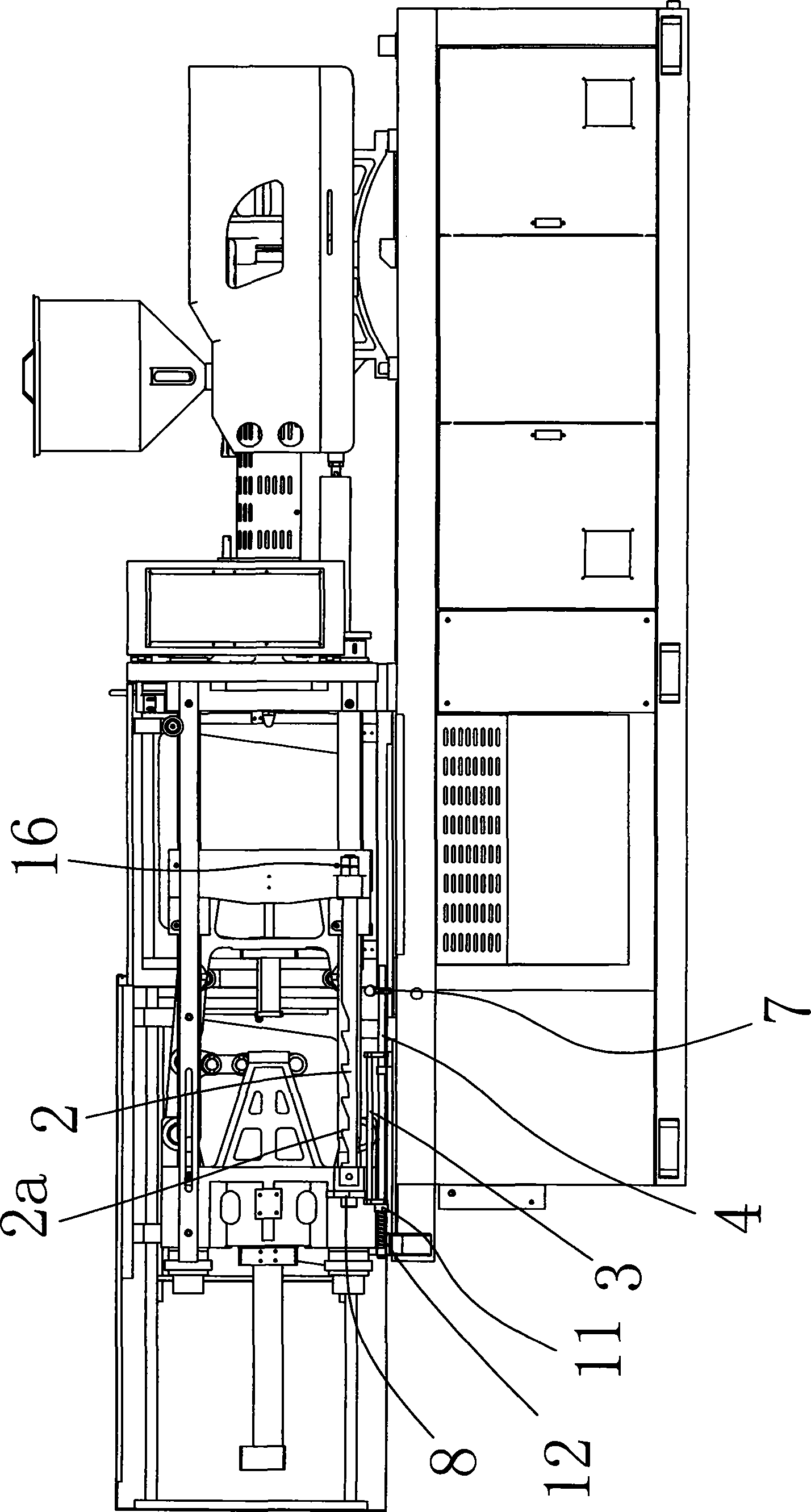
[0017] In the figure, the movable wall 1 of the injection molding machine; the mechanical safety lever 2; the pawl 2a; the sliding rod 3; the mechanical safety rotary lever 4; the front limit block 5; the rear limit block 6; 8; the first mechanical safety connecting rod 9; the second mechanical safety connecting rod 10; positioning ring 11; return spring 12; front fixed block 13; rear fixed block 14; bumper pressure block 15;

[0018] Such as figure 1 and figure 2 As shown, the mechanical safety mechanism of the injection molding machine includes a mechanical safety lever 2 fixedly connected with the movable wall 1 of the injection molding machine, a sliding rod 3 and a mechanical safety rotary lever 4, and the injection...


PUM


Abstract

The invention belongs to the technical field of injection molding machines and provides a mechanical safety mechanism of an injection molding machine. The mechanical safety mechanism of the injection molding machine comprises a mechanical safety rod, a sliding rod and a mechanical safety rotary rod, wherein the mechanical safety rod is fixedly connected with a movable wall of the injection molding machine. A front limiting block and a rear limiting block are respectively arranged on the injection molding machine, the mechanical safety rotary rod is penetratingly arranged between the front limiting block and the rear limiting block, the sliding rod is in parallel connection with the mechanical safety rotary rod, a door control safety pulley is fixed on the mechanical safety rotary rod, and a mechanical safety stopper matched with the mechanical safety rod is fixed on the sliding rod. The mechanical safety mechanism of the injection molding machine has the advantages that high safety is achieved, and a pawl of the mechanical safety rod is locked by the mechanical safety stopper to limit transverse movement of the mechanical safety rod, so that the injection molding machine cannot perform the mold closing action so as to realize shutdown protection, and personal injuries can be effectively avoided.

Description

technical field [0001] The invention belongs to the technical field of injection molding machines, and relates to a mechanical safety mechanism of an injection molding machine. Background technique [0002] In order to ensure the safety of the injection molding machine, the injection molding machine is equipped with a safety door. After the safety door is opened, the injection molding machine cannot perform mold closing action to realize shutdown protection. In this way, a mechanical safety structure needs to be added to avoid danger. The existing injection molding After the safety door is closed, the mechanical safety mechanism mainly uses the pull stud installed on the guide rail, and uses the raised part of the pull stud to block the door wheel, so as to realize the mechanical insurance. Patent Document [Notice No.: CN201506021] discloses an anti-retraction device for safety doors of injection molding machines, including cup head screws, springs, a first anti-retraction m...

Claims


Application Information

Patent Timeline
Patent Type & Authority Applications(China)
IPC IPC(8): B29C45/84
Inventor 蔡高峰
Owner NINGBO HAIRI PLASTIC MACHINERY
Learn More