Three-dimensional multi-directional displacement comb tooth telescopic device

A three-dimensional multi-directional, telescopic device technology, used in bridge parts, bridge materials, bridges, etc., can solve the problems of untimely maintenance, complicated repair and replacement construction, loss of expansion and contraction function of comb tooth gaps, etc. Synchronization, ensuring bridge expansion and traffic safety, and alleviating the effect of bridge damage

Pending Publication Date: 2020-02-28
魏红雨
View PDF0 Cites 2 Cited by
  • Summary
  • Abstract
  • Description
  • Claims
  • Application Information

AI Technical Summary

Problems solved by technology

The current multi-directional shifting comb telescopic device mainly uses elastic materials, such as rubber pads, to buffer the vertical force. The elastic materials are easy to age and have a short service life. Timely clean up the various reasons that affect the bridge's telescopic displacement and the accumulated energy cannot be effectively released. As a result, many telescopic devices are damaged every year and the back wall of the bridge abutment is severely damaged, and the beam head and girder are crushed and scrapped, causing safety hazards and traffic accidents. ; Ordinary comb-tooth plate expansion joints are fixed and installed with bolts. Due to various reasons such as bridge creep and disturbance changes, the multi-directional displacement force of the expansion joints cannot be effectively released and twisted and deformed. Finally, the fixing bolts loosen and fall off and fail, resulting in The expansion function of the comb joint is limited, the expansion function is lost and the expansion joint is lost, which will affect the driving safety of the vehicle and damage the bridge, and the maintenance and replacement in the later period is extremely complicated and difficult to clean up. The maintenance time is long

Method used


Image

  • Three-dimensional multi-directional displacement comb tooth telescopic device
  • Three-dimensional multi-directional displacement comb tooth telescopic device
  • Three-dimensional multi-directional displacement comb tooth telescopic device

Examples


Embodiment Construction

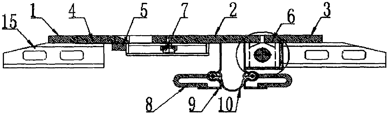
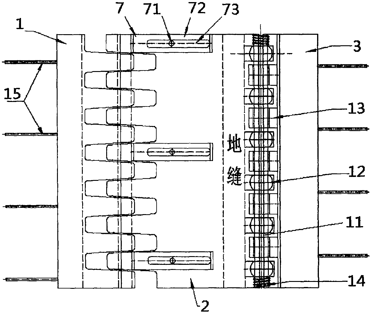
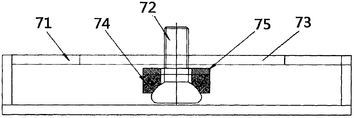
[0022] refer to figure 1 , figure 2 , image 3 , Figure 4 , a three-dimensional multi-directional shifting comb telescopic device, including a corresponding comb main tooth plate 2, a comb tooth auxiliary tooth plate 1, a main tooth fixing plate 3, and the main tooth fixing plate 3 and the comb main tooth plate 2 are movable Connection, the stainless steel plate 4 is welded under the comb-tooth sub-tooth plate 1, the support beam 5 presses the stainless steel plate 4 and is welded on the comb teeth of the comb-tooth sub-tooth plate, and the comb main tooth plate 2 and the comb-tooth sub-tooth plate 1 stretching process will be kept on the same level, and will not be out of joint. There is a guide groove 73 on the limit box 71 on the limit device 7, and the round head bolt 72 is fastened under the comb tooth main tooth plate 2. The round head bolt 72 can move along the guide groove 73, and is used to limit the comb tooth main tooth plate. The telescoping and vertical lift...


PUM


Abstract

The invention discloses a three-dimensional multi-directional displacement comb tooth telescopic device, and belongs to the field of bridge expansion joint devices. The three-dimensional multi-directional displacement comb tooth telescopic device includes a corresponding comb tooth main tooth plate, a comb tooth auxiliary tooth plate, a main tooth fixing plate, the main tooth fixing plate is movably connected with the comb tooth main tooth plate, a multi-directional displacement device is mounted under the joint between the main tooth fixing plate and the comb tooth main tooth plate, the multi-directional displacement device includes a spherical universal bearing, a connecting shaft, and an anchoring connection plate, the spherical universal bearing and the anchoring connection plate are staggered and distributed on the same horizontal plane, and the connecting shaft connects the spherical universal bearing and the anchoring connection plate together and connects the main tooth fixingplate and the comb tooth main tooth plate together at the same time. The three-dimensional multi-directional displacement comb tooth telescopic device has the advantageous that shock resistance is extremely high, garbage is self-cleaned, mounting is conducted without bolts, synchronous movement in the longitudinal direction, the horizontal direction, and the vertical direction is realized, and theservice life is long.

Description

technical field [0001] The invention discloses a three-dimensional multidirectional displacement comb tooth expansion device, which belongs to the field of bridge expansion joint devices. Background technique [0002] The telescopic device is an important component of the bridge. The rationality of its performance directly affects the bridge's telescopic performance, bridge stability and service life, and plays a role in ensuring the comfort and safety of vehicles in traffic. The current multi-directional shifting comb telescopic device mainly uses elastic materials, such as rubber pads, to buffer the vertical force. The elastic materials are easy to age and have a short service life. Timely clean up the various reasons that affect the bridge's telescopic displacement and the accumulated energy cannot be effectively released. As a result, many telescopic devices are damaged every year and the back wall of the bridge abutment is severely damaged, and the beam head and girder ...

Claims


Application Information

Patent Timeline
Patent Type & Authority Applications(China)
IPC IPC(8): E01D19/06E01D101/30
CPCE01D19/06E01D2101/30
Inventor 魏红雨
Owner 魏红雨
Why Eureka
Try Eureka