Multifunctional control valve

A multi-functional control valve and valve body technology, applied in multi-way valves, valve devices, filtration and separation, etc., can solve the problems of continuous supply of raw water, small flow channels of valve plates, etc., and achieve large water flow and enlarged flow channels The effect of width

Active Publication Date: 2012-09-19
YUYAO YADONG PLASTIC
View PDF4 Cites 12 Cited by
  • Summary
  • Abstract
  • Description
  • Claims
  • Application Information

AI Technical Summary

Problems solved by technology

[0004] The technical problem to be solved by the present invention is to provide a multi-functional control valve to overcome the defects of the existing planar filter valve technology that the flow path of the valve plate is small or that raw water cannot be continuously supplied during flushing

Method used


Image

  • Multifunctional control valve
  • Multifunctional control valve
  • Multifunctional control valve

Examples


Embodiment 1

[0049] The scheme of continuous water supply during flushing, single-ring four-hole fixed valve plate, and single water inlet channel.

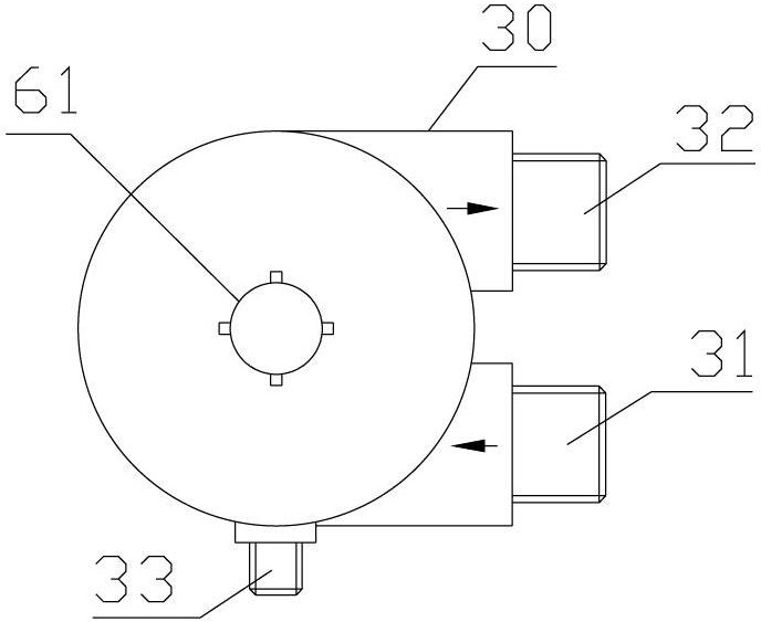
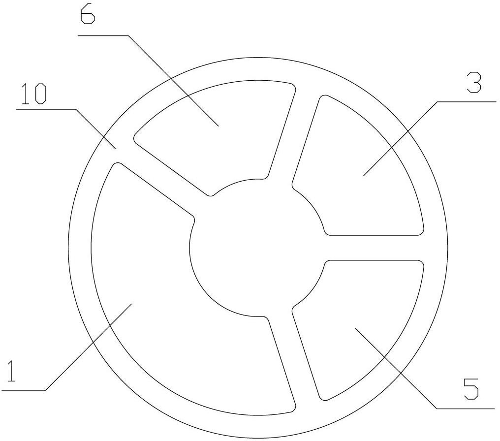
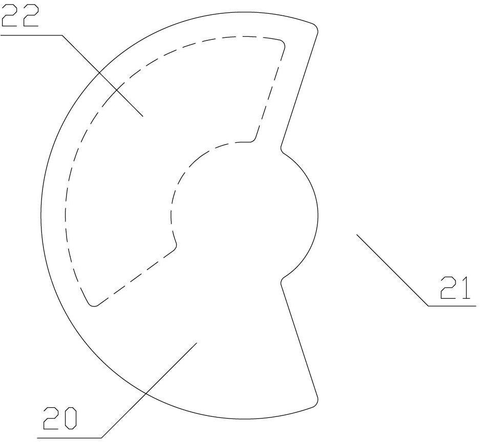
[0050] like Figure 1-4 As shown, use Figure 2-3The fixed-moving valve combination shown is a multi-functional control valve, including a valve body 30, a cover 60, a valve stem 61, a fixed valve piece 10 and a moving valve piece 20 placed in the valve body 30 and adopting end face rotation and sealing fit. , the movable valve plate 20 is connected with the valve stem 61, the valve body 30 is provided with a raw water inlet 31, a clean water outlet 32, a sewage discharge interface 33, a filter element first interface 38 and a filter element second interface 39, and the fixed valve plate 10 is provided with: The first interface channel 1 of the filter element, the second interface channel 3 of the filter element, the fifth through hole 5 and the sixth through hole 6, in the control valve, the first interface channel 1 of the filter element c...

Embodiment 2

[0056] The scheme of no water supply during flushing, single-ring six-hole fixed valve plate, and double water inlet channels.

[0057] like figure 1 , Figure 10-12 As shown, use Figure 10-11 The fixed-moving valve combination shown is a multi-functional control valve, including a valve body 30, a cover 60, a valve stem 61, a fixed valve piece 10 and a moving valve piece 20 placed in the valve body 30 and adopting end face rotation and sealing fit. , the movable valve plate 20 is connected with the valve stem 61, the valve body 30 is provided with a raw water inlet 31, a clean water outlet 32, a sewage discharge interface 33, a filter element first interface 38 and a filter element second interface 39, and the fixed valve plate 10 is provided with: The first through hole 1B, the second through hole 2B, the third through hole 3B, the fourth through hole 4B, the fifth through hole 5B and the sixth through hole 6B, in the control valve, the first through hole 1B and the secon...

Embodiment 3

[0063] No water supply during flushing, single-ring four-hole fixed valve plate, and single water inlet channel.

[0064] like figure 1 , Figure 18-19 , Figure 12 As shown, use Figure 18-19The fixed-moving valve combination shown is a multi-functional control valve, including a valve body 30, a cover 60, a valve stem 61, a fixed valve piece 10 and a moving valve piece 20 placed in the valve body 30 and adopting end face rotation and sealing fit. , the movable valve plate 20 is connected with the valve stem 61, the valve body 30 is provided with a raw water inlet 31, a clean water outlet 32, a sewage discharge interface 33, a filter element first interface 38 and a filter element second interface 39, and the fixed valve plate 10 is provided with: The first interface channel 1C of the filter element, the second interface channel 3C of the filter element, the fifth through hole 5C and the sixth through hole 6C, in the control valve, the first interface channel 1C of the fil...


PUM


Abstract

The invention discloses a multifunctional control valve, which comprises a valve body, a cap, a valve rod, a fixed valve plate and a movable valve plate, the fixed valve plate and the movable valve plate are arranged in the valve body, and adopt end face rotary seal, the movable valve plate is connected with the valve rod, the control valve is provided with a raw water inlet, a clean water outlet, a drain connector, a first filter element connector and a second filter element connector, and the fixed valve plate is provided with a first filter element connector passage, a second filter element connector passage, a fifth through hole and a sixth through hole; in the control valve, the first filter element connector passage communicates with the first filter element connector, the second filter element connector passage communicates with the second filter element connector, the fifth through hole communicates with the clean water outlet, and the sixth through hole communicates with the drain connector; and the movable valve plate is provided with a water inlet passage which communicates with the raw water inlet, and is also provided with a communicating blind hole. The multifunctional control valve has the advantages that: the flow passage in the valve body is enlarged, so that water flow is enlarged, and raw water can be supplied during backward washing and forward washing.

Description

technical field [0001] The invention relates to a multifunctional control valve for water treatment system. Background technique [0002] In the existing industrial or domestic water treatment technology, multifunctional control valves are often used to realize functions such as filtering, backwashing, and positive washing of the filter element. In recent years, planar multi-function control valves have increasingly become one of the mainstream valve types of multi-function control valves. First of all, due to the complexity of the design of the planar valve plate and internal flow channel and the limitation of the area of ​​the valve plate, it is difficult to design a planar valve with a large channel; , Supply untreated raw water while washing, the existing planar multifunctional control valve has been difficult to meet this demand. Contents of the invention [0003] (1) Technical problems to be solved [0004] The technical problem to be solved by the present inventi...

Claims


Application Information

Patent Timeline
Patent Type & Authority Applications(China)
IPC IPC(8): F16K11/074B01D35/12
Inventor 胡霄宗胡继宗涂泽红
Owner YUYAO YADONG PLASTIC
Why Eureka
Try Eureka