Flow controller and water treatment system

A technology of flow controller and flow surface, which is applied in the field of flow controller, can solve the problems of continuous supply of raw water and small valve flow channels, etc., and achieve the effects of reasonable area design, material cost saving and reasonable arrangement

Active Publication Date: 2017-05-10
胡霄宗 +2
View PDF6 Cites 0 Cited by
  • Summary
  • Abstract
  • Description
  • Claims
  • Application Information

AI Technical Summary

Problems solved by technology

[0008] The technical problem to be solved by the present invention is to provide a multi-functional control valve to overcome the defects of the existing planar filter valve technology that the flow path of the valve plate is small or that raw water cannot be continuously supplied during flushing

Method used


Image

  • Flow controller and water treatment system
  • Flow controller and water treatment system
  • Flow controller and water treatment system

Examples


Embodiment 1

[0278] The scheme of continuous water supply during flushing, single-ring four-hole fixed valve plate, and single water inlet channel.

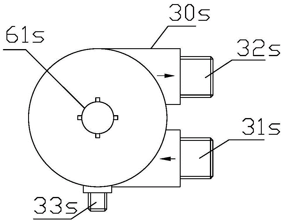
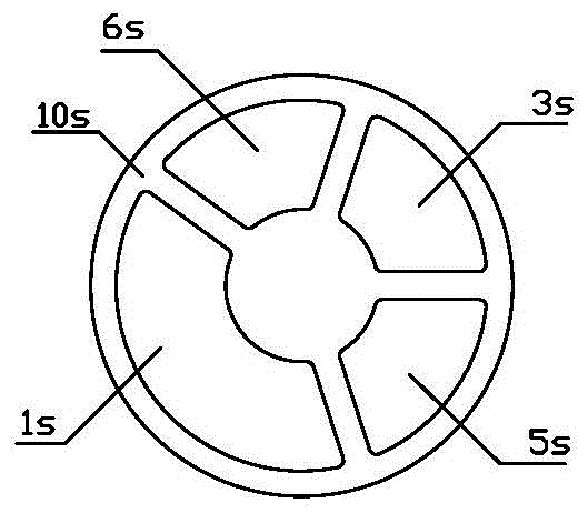
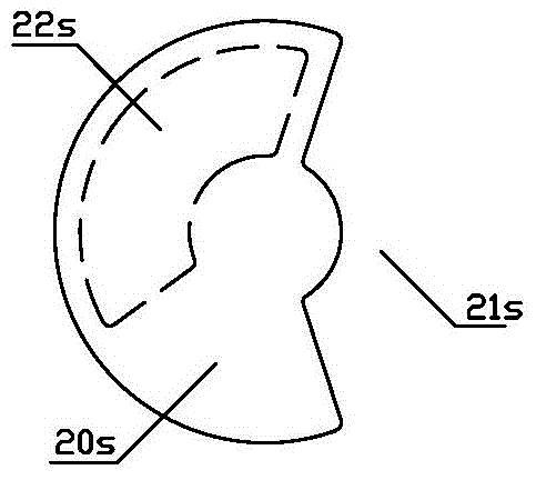
[0279] Such as Figure 1 to Figure 4 As shown, use Figure 2 to Figure 3 The fixed-moving valve combination shown is a multi-functional control valve, including a valve body 30s, a cover 60s, a valve stem 61s, a fixed valve piece 10s and a moving valve piece 20s placed in the valve body 30s and fitted with end face rotation and sealing. , the moving valve plate 20s is connected to the valve stem 61s, the valve body 30s is provided with a raw water inlet 31s, a purified water outlet 32s, a sewage discharge interface 33s, a filter element first interface 38s and a filter element second interface 39s, and the fixed valve plate 10s is provided with: The first interface channel 1s of the filter element, the second interface channel 3s of the filter element, the fifth through hole 5s and the sixth through hole 6s, in the control valve, the first i...

Embodiment 2

[0285] The scheme of no water supply during flushing, single-ring six-hole fixed valve plate, and double water inlet channels.

[0286] Such as figure 1 , Figure 10 to Figure 12 As shown, use Figure 10 to Figure 11 The fixed-moving valve combination shown is a multi-functional control valve, including a valve body 30s, a cover 60s, a valve stem 61s, a fixed valve piece 10s and a moving valve piece 20s placed in the valve body 30s and fitted with end face rotation and sealing. , the moving valve plate 20s is connected to the valve stem 61s, the valve body 30s is provided with a raw water inlet 31s, a purified water outlet 32s, a sewage discharge interface 33s, a filter element first interface 38s and a filter element second interface 39s, and the fixed valve plate 10s is provided with: The first through hole 102s, the second through hole 202s, the third through hole 302s, the fourth through hole 402s, the fifth through hole 502s and the sixth through hole 602s, in the contr...

Embodiment 3

[0292] No water supply during flushing, single-ring four-hole fixed valve plate, and single water inlet channel.

[0293] Such as figure 1 , Figure 18 , Figure 19 and Figure 12 As shown, use Figure 18 to Figure 19 The fixed-moving valve combination shown is a multi-functional control valve, including a valve body 30s, a cover 60s, a valve stem 61s, a fixed valve piece 10s and a moving valve piece 20s placed in the valve body 30s and fitted with end face rotation and sealing. , the moving valve plate 20s is connected to the valve stem 61s, the valve body 30s is provided with a raw water inlet 31s, a purified water outlet 32s, a sewage discharge interface 33s, a filter element first interface 38s and a filter element second interface 39s, and the fixed valve plate 10s is provided with: The first interface channel 103s of the filter element, the second interface channel 303s of the filter element, the fifth through hole 503s and the sixth through hole 603s. The channel 3...


PUM


Abstract

A flow controller applicable for controlling multi-directional flow of a fluid, comprising a first flow control component (10 and 10A-H) a second flow control component (20 and 20A-H), and a housing (30 and 30A-H). The second flow control component (20 and 20A-H) is suitable to be arranged at the first flow control component (10 and 10A-H) and be accommodated within a first accommodation chamber (310 and 310A-H) formed by the housing (30 and 30A-H). A user can rotate the second flow control component (20 and 20A-H) to allow channels arranged at the first flow control component (10 and 10A-H) to connect selectively to channels of the second flow control component (20 and 20A-H), thus controlling the flow of different water flows. The flow controller has the advantages of a simple structure, reduced manufacturing costs, convenient use, and reliable performance.

Description

technical field [0001] The present invention relates to a fluid treatment system, in particular to a flow controller, wherein the flow controller is suitable for controlling the flow of various fluids, so as to realize the fluid treatment function of the fluid system, and the user can adjust the flow controller Movement of the second flow control element relative to its first flow control element regulates and controls flow of water in different directions in the fluid treatment system. Background technique [0002] Fluid control and / or treatment systems, such as water treatment systems, are common in both industrial production and people's real life. A common fluid treatment system generally includes a flow controller and a processing unit, wherein the flow controller is suitable for controlling the flow of fluid to the treatment unit, and the treatment unit is suitable for treating the fluid to be treated to obtain the treated fluid. When the fluid treatment system treats...

Claims


Application Information

Patent Timeline
IPC IPC(8): F16K11/074
CPCF16K11/074
Inventor 胡霄宗胡继宗涂泽红
Owner 胡霄宗
Why Eureka
Try Eureka