Optical regulation lens frame suitable for mobile process full-solid state high power laser

A high-power laser and mobile processing technology, applied in the direction of laser parts, optics, optical components, etc., can solve the problem of lens cooling and other problems, and achieve the effect of reliable positioning, small deformation and stable positioning

Inactive Publication Date: 2009-07-01
DALU AUTOMATION TECH SHENYANG
View PDF0 Cites 25 Cited by
  • Summary
  • Abstract
  • Description
  • Claims
  • Application Information

AI Technical Summary

Problems solved by technology

[0005] The purpose of the present invention is to solve the problems of poor stability and no corresponding cooling device in the currently commonly used lasers, and to provide an improved positioning structure, increased stability of the mirror frame, and a cooling device to solve the problem of high-power The cooling problem of the laser lens is suitable for the optical adjustment frame suitable for mobile processing of all solid-state high-power lasers required by frequent mobile processing

Method used


Image

  • Optical regulation lens frame suitable for mobile process full-solid state high power laser
  • Optical regulation lens frame suitable for mobile process full-solid state high power laser
  • Optical regulation lens frame suitable for mobile process full-solid state high power laser

Examples


Embodiment Construction

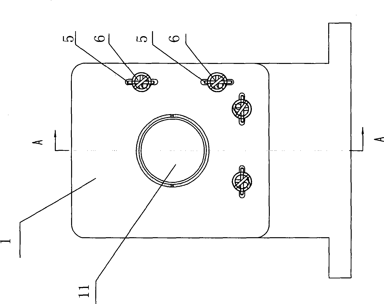
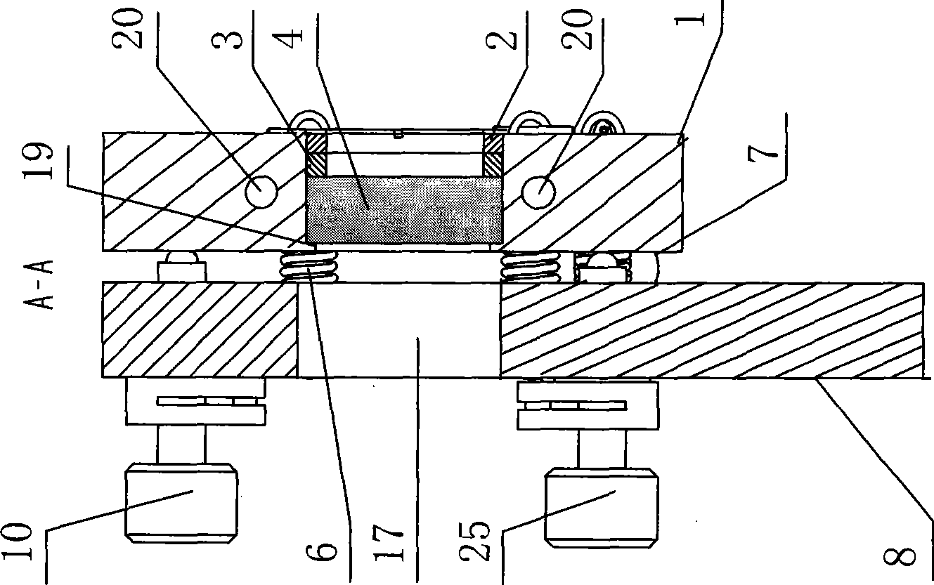
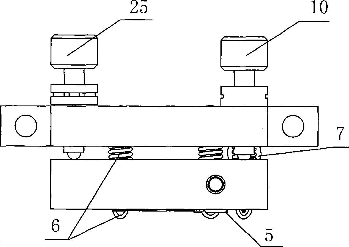
[0039] An optical adjustment mirror frame suitable for mobile processing of all solid-state high-power lasers, including a mirror frame 1, a bracket 8, four tension springs 6, a retaining ring 3, a retaining ring 2, and a fine-tuning screw pair 10; figure 1Shown in -16, the front center of the picture frame 1 is provided with a lens hole 11, and a card platform 19 is arranged in the lens hole 11, and a lens 4 is installed on the card platform 19, and a copper retaining ring 3 is installed on the outside of the lens 4. A copper retaining ring 2 is installed on the outside of the copper retaining ring 3, and the copper retaining ring 2 is rotatably connected with the inner wall of the lens hole 11 through threads, and the copper retaining ring 2 is used to press the copper retaining ring 2 through the threads by means of end face compression. The baffle ring 3 of copper, the baffle ring 3 of copper tightly presses the eyeglass 4 again; Four picture frame tension spring holes 12 a...


PUM


Abstract

An optical adjusting mount capable of movably processing all-solid-state high power lasers comprises a frame, a support and a fine adjustment screw pair, wherein a lens hole of the frame is internally equipped with a baffle ring, a retainer ring is disposed on the front of the baffle ring, four tension spring holes are positioned on the frame, the back face of the frame is equipped with a V-type groove, a concave groove and a ball tapered-groove, the side face of the frame is equipped with a cooling water inlet and an outlet, the support is equipped with four tension spring holes, two holes for the fine adjustment screw pair and a ball tapered-groove which correspond to the frame, the frame and the support are connected through tension springs, each of the ball tapered-grooves of the frame and the support are inlaid with a ball, the fine adjustment screw pair is respectively mounted in the two holes for the fine adjustment screw pair of the support, the front ends of the fine adjustment screw pair are respectively located in the V-type groove and the groove. The optical adjusting mount has the advantages of scientific reasonable design, compact structure, low material consumption and low cost, further utilizes the baffle ring made of low-hardness fine heat conductivity red copper to press the lens on the end face, thereby effectively reducing the lens temperature, and utilizes the V-type groove and the ball for positioning, thereby realizing stable and reliable groove limiting.

Description

technical field [0001] The invention relates to parts of a laser, in particular to an optical adjustment mirror frame suitable for mobile processing of an all-solid-state high-power laser. Background technique [0002] The cavity mirror in the laser is an important component for the generation of laser light and the transmission of the laser light in the optical cavity. The relative position requirements of each lens are very high. A slight deviation will cause the deviation of the laser optical path, resulting in the failure of the laser to generate laser light normally. personal accident. This requires that the frame on which the lenses are mounted should be flexible and adjustable in space, and have a stable structure. [0003] However, the frame commonly used at home and abroad is mainly a ball spring structure, and the structure is relatively thin. Most of the lens fixing methods are fixed on the frame by side screws, and the bracket of the frame is fixed on the base. ...

Claims


Application Information

Patent Timeline
Patent Type & Authority Applications(China)
IPC IPC(8): G02B7/00H01S3/02
Inventor 张春杰单少聪刘齐芳
Owner DALU AUTOMATION TECH SHENYANG
Why Eureka
Try Eureka