Multifunctional control valve
A multi-functional control valve and control valve technology, applied in multi-way valves, valve devices, engine components, etc., can solve the problems of small valve flow channels and continuous supply of raw water, etc., to achieve large water flow and enlarged flow channels The effect of width
- Summary
- Abstract
- Description
- Claims
- Application Information
AI Technical Summary
Problems solved by technology
Method used
Image
Examples
Embodiment 1
[0054] A solution for continuous water supply during flushing and draining through the valve stem to the drain connection on the cover.
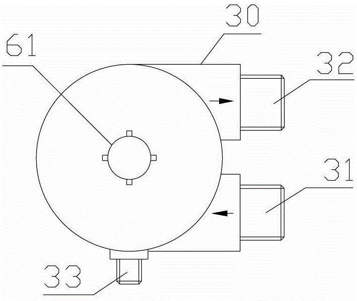
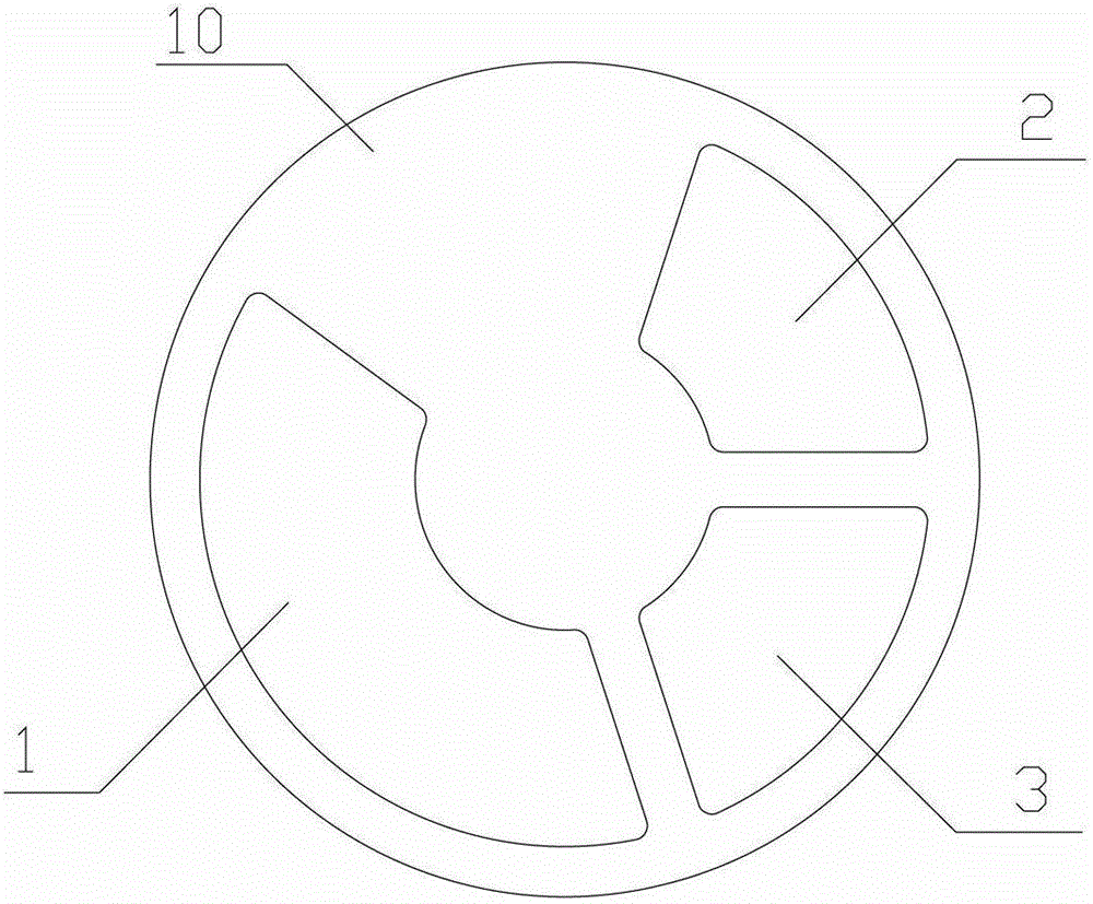
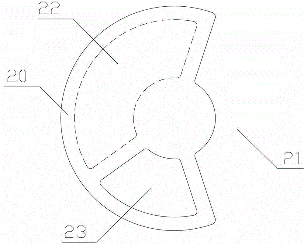
[0055]Such as Figure 1-4 As shown, use Figure 2-3 The fixed-moving valve combination shown is a multi-functional control valve, including a valve body 30, a cover 60, a valve stem 61, a fixed valve piece 10 and a moving valve piece 20 placed in the valve body 30 and adopting end face rotation and sealing fit. , the movable valve plate 20 is connected with the valve stem 61, the valve body 30 is provided with a raw water inlet 31, a purified water outlet 32, a filter element first interface 38 and a filter element second interface 39, and the cover is provided with a sewage interface 33; the fixed valve plate 10 There are: the first through hole 1, the second through hole 2 and the third through hole 3. In the control valve, the first through hole 1 communicates with the first interface 38 of the filter element, and the second through hole...
Embodiment 2
[0064] The scheme of continuously supplying water during flushing and discharging sewage through the fourth through hole of the fixed valve plate.
[0065] Such as figure 1 , Figure 10-12 As shown, use Figure 10-11 The fixed-moving valve combination shown is a multi-functional control valve, including a valve body 30, a cover 60, a valve stem 61, a fixed valve piece 10 and a moving valve piece 20 placed in the valve body 30 and adopting end face rotation and sealing fit. , the movable valve plate 20 is connected with the valve stem 61, and the valve body 30 is provided with a raw water inlet 31, a clean water outlet 32, a sewage discharge interface 33, a filter element first interface 38 and a filter element second interface 39; the fixed valve plate 10 is provided with: The first through hole 1, the second through hole 2 and the third through hole 3, in the control valve, the first through hole 1 communicates with the first port 38 of the filter element, and the second th...
Embodiment 3
[0073] The scheme of not supplying raw water during flushing and discharging sewage through the fourth through hole of the fixed valve plate.
[0074] Such as figure 1 , Figure 18-20 As shown, use Figure 18-19 The fixed-moving valve combination shown is a multi-functional control valve, including a valve body 30, a cover 60, a valve stem 61, a fixed valve piece 10 and a moving valve piece 20 placed in the valve body 30 and adopting end face rotation and sealing fit. , the movable valve plate 20 is connected with the valve stem 61, and the valve body 30 is provided with a raw water inlet 31, a clean water outlet 32, a sewage discharge interface 33, a filter element first interface 38 and a filter element second interface 39; the fixed valve plate 10 is provided with: The first through hole 1C, the second through hole 2C and the third through hole 3C, in the control valve, the first through hole 1C communicates with the first interface 38 of the filter element, and the secon...
PUM
 Abstract
Description
Claims
Application Information
 - R&D
- Intellectual Property
- Life Sciences
- Materials
- Tech Scout
- Unparalleled Data Quality
- Higher Quality Content
- 60% Fewer Hallucinations
Browse by: Latest US Patents, China's latest patents, Technical Efficacy Thesaurus, Application Domain, Technology Topic, Popular Technical Reports.
© 2025 PatSnap. All rights reserved.Legal|Privacy policy|Modern Slavery Act Transparency Statement|Sitemap|About US| Contact US: help@patsnap.com


