Liquid injection flow channel

A jet flow and liquid technology, applied in the field of MEMS technology, can solve the problems of insufficient ink supply speed and untimely ink supply of the print head, etc., and achieve the effects of timely ink supply, increased capillary area, and good printing quality

Active Publication Date: 2021-07-02
苏州印科杰特半导体科技有限公司
View PDF13 Cites 1 Cited by
  • Summary
  • Abstract
  • Description
  • Claims
  • Application Information

AI Technical Summary

Problems solved by technology

[0005] The technical problem to be solved by the present invention is to solve the problems that the ink supply of the existing printing head is not timely, the ink supply speed is not enough, etc.

Method used


Image

  • Liquid injection flow channel
  • Liquid injection flow channel
  • Liquid injection flow channel

Examples


Embodiment 1

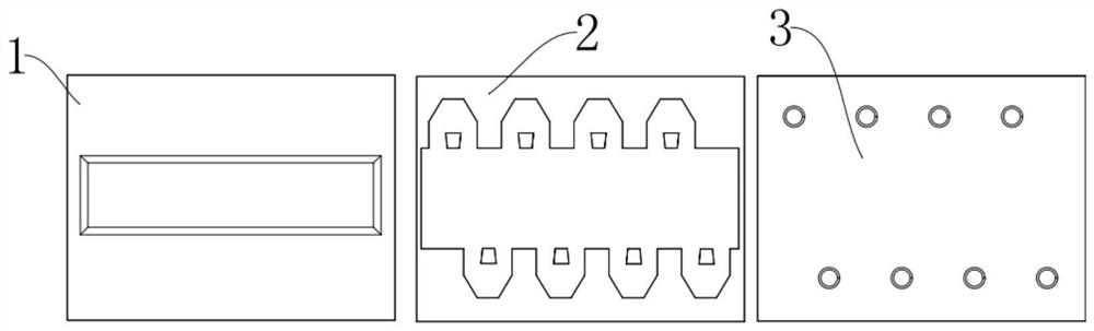
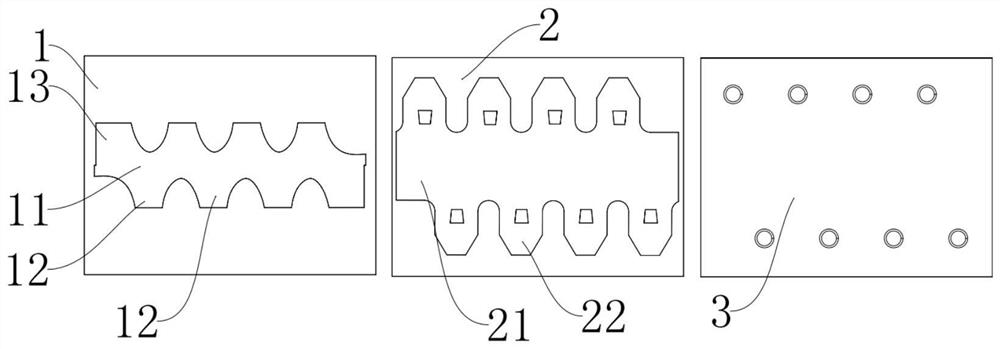
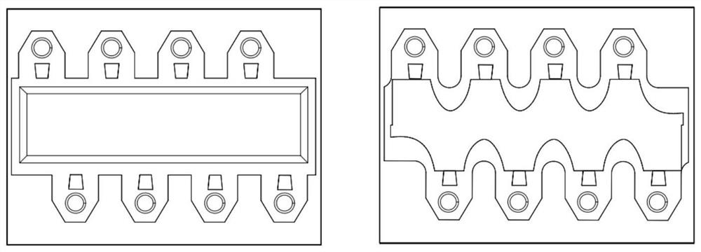
[0033] Such as figure 2 , image 3 As shown in the right figure of the figure: a liquid jet channel, including a base layer 1, a chamber wall layer 2 and an orifice layer 3, the middle part of the base layer 1 is provided with an ink inlet channel, and the chamber wall layer 2 is provided with a pressure chamber, The orifice layer 3 is provided with an orifice, and the base layer 1 is provided with a chamber wall layer 2 and an orifice layer 3 in sequence, and the pressure chamber is respectively communicated with the ink inlet channel and the nozzle hole, and the cross section of the ink inlet channel is Curved type, which includes a base rectangular portion 11, a base extension portion a12 and a base extension portion b13, a plurality of base extension portions a12 are respectively arranged on both sides of the width direction of the base rectangle portion 11, and the two ends of the length direction of the base rectangle portion 11 are One base extension b13 is respective...


PUM


Abstract

The invention discloses a liquid injection flow channel, and belongs to the technical field of MEMS processes. The liquid injection flow channel comprises a substrate layer, a cavity wall layer and a spray hole layer, wherein an ink inlet channel is formed in the middle of the substrate layer, a pressure cavity is formed in the cavity wall layer, spray holes are formed in the spray hole layer, the cavity wall layer and the spray hole layer are sequentially arranged on the substrate layer, the pressure cavity communicates with the ink inlet channel and the spray holes respectively, and the cross section of the ink inlet channel is in a curve shape, the substrate layer comprises a substrate rectangular part, substrate extension parts a and substrate extension parts b, the multiple substrate extension parts a are arranged on the two sides of the substrate rectangular part in the width direction respectively, and the substrate extension parts b are arranged at the two ends of the substrate rectangular part in the length direction respectively. According to the liquid injection flow channel, the printing quality is better, the printing precision is higher, ink is supplied in time, a runner can be completely filled, and the ink jetting quality is improved.

Description

technical field [0001] The invention discloses a liquid injection channel, which belongs to the technical field of MEMS technology. Background technique [0002] The main element of the print head of an inkjet printer is a nozzle plate that includes ink supply channels for ejecting ink from the print head, ejection chambers and ejection ports. Due to the popularization and use of inkjet printers, in order to improve inkjet efficiency and reduce manufacturing costs, the nozzle plate has undergone a major design transformation. In an attempt to accommodate high-speed printing and high-definition printed images, the design of the nozzle plate also needs to be changed. Although improvements in printhead design have enabled printheads to achieve higher resolution at higher print speeds, such improvements pose new problems relative to the manufacturing cost of the nozzle plate because of the complexity of the design. Therefore, for the design of more complex parts involving flow...

Claims


Application Information

Patent Timeline
Patent Type & Authority Applications(China)
IPC IPC(8): B41J2/14
CPCB41J2/14016B41J2/1404
Inventor 陆安江张孝宇
Owner 苏州印科杰特半导体科技有限公司
Why Eureka
Try Eureka