Stationary cam cylinder

A technology for fixing cams and cam barrels, applied in installation, optics, instruments, etc., can solve problems such as abnormal sound and jamming of the lens, and achieve the effect that it is not easy to shift

Active Publication Date: 2012-09-19
ASIA OPTICAL CO INC
View PDF8 Cites 2 Cited by
  • Summary
  • Abstract
  • Description
  • Claims
  • Application Information

AI Technical Summary

Problems solved by technology

[0005] The technical problem to be solved by the present invention is to provide a fixed cam barrel that will not cause abnormal noise when the lens is adjusted or zoomed, aiming at the defects in the prior art that the fixed cam barrel will cause abnormal noise or jamming of the lens during operation. sound or stuck

Method used


Image

  • Stationary cam cylinder
  • Stationary cam cylinder
  • Stationary cam cylinder

Examples


Embodiment Construction

[0015] In order to illustrate the present invention more clearly, preferred embodiments are given and described in detail with accompanying drawings as follows.

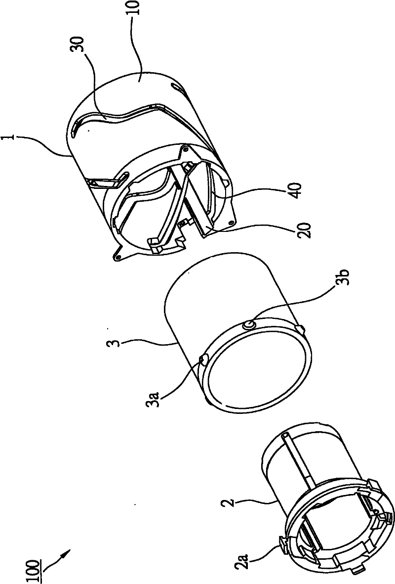
[0016] see figure 2 , the lens module 100 of the preferred embodiment of the present invention includes a fixed cam barrel 1 , a lens barrel 2 and a rotating cam barrel 3 . in:

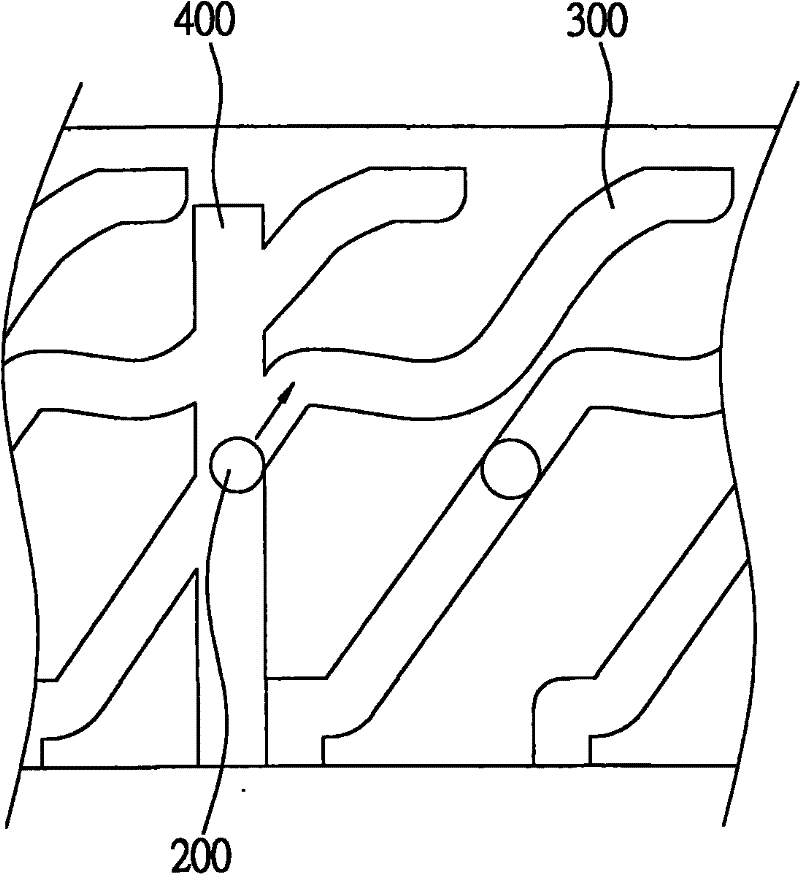
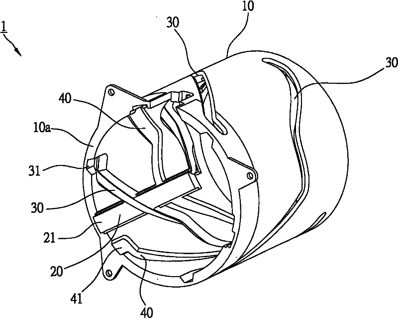
[0017] continued Figure 3 to Figure 5 , the fixed cam cylinder 1 includes a cylinder body 10 , and three guide grooves 20 , three first actuation grooves 30 and three second actuation grooves 40 arranged on the inner wall of the cylinder body 10 . The cylinder body 10 has a first end 10a, and each of the guiding slots 20 has a first opening 21 formed at the first end 10a. In addition, in this embodiment, each of the guide grooves 20 goes straight into the groove, but it is not limited thereto, and the guide grooves 20 can also be other types of grooves in terms of design.

[0018] These first actuation grooves 30 run through the cylind...


PUM


Abstract

The invention relates to a stationary cam cylinder which comprises a cylinder body, a guide slot, a first action slot and a second action slot, wherein the guide slot is formed on the cylinder body; the first action slot is formed on the cylinder body and comprises a first slot section and a second slot section which are communicated with each other; the first slot section is staggered with the guide slot; the first slot section of the first action slot is wider than the second slot section of the first action slot; the second action slot is formed on the cylinder body and also comprises a first slot section and a second slot section which are communicated with each other; the second slot section of the second action slot is staggered with the guide slot; the second slot section of the second action slot is wider than the first slot section of the second action slot.

Description

technical field [0001] The present invention is related to the lens structure, and more specifically refers to a fixed cam barrel. Background technique [0002] The fixed cam cylinder used in the known lens module usually has several guide grooves distributed equidistantly on the cylinder wall, and several actuating grooves respectively interlaced with the guide grooves and distributed with equal widths and unequal distances. The lens barrel of the lens module has several protruding shafts combined with these actuating grooves, so that the lens barrel can be moved by using the actuating grooves, so that the lens can be retracted to achieve the purpose of focusing or zooming. These guide grooves are designed to be distributed at unequal distances so that when one of the protruding shafts passes through the intersection of the actuating groove and the guiding groove and is suspended in the air, the other several protruding shafts will be combined with the corresponding actuati...

Claims


Application Information

Patent Timeline
Patent Type & Authority Applications(China)
IPC IPC(8): G02B7/04
Inventor 陈峻佃
Owner ASIA OPTICAL CO INC
Why Eureka
Try Eureka