

Clamping device and core passing machine using clamping device
A clamping device and chuck technology, which is applied in the field of CNC machine tools, can solve problems such as parts damage, and achieve the effect of improving machining accuracy and preventing deviation
- Summary
- Abstract
- Description
- Claims
- Application Information
AI Technical Summary
Problems solved by technology
Method used
Image

Examples
Embodiment 1
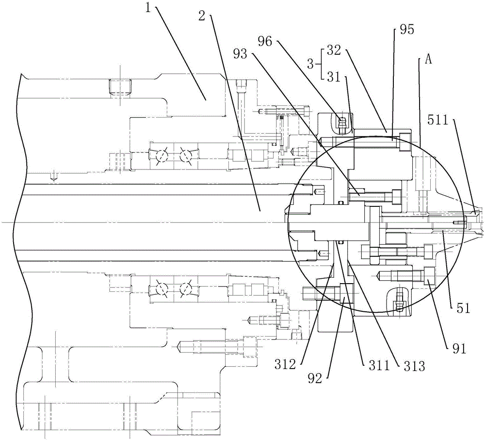
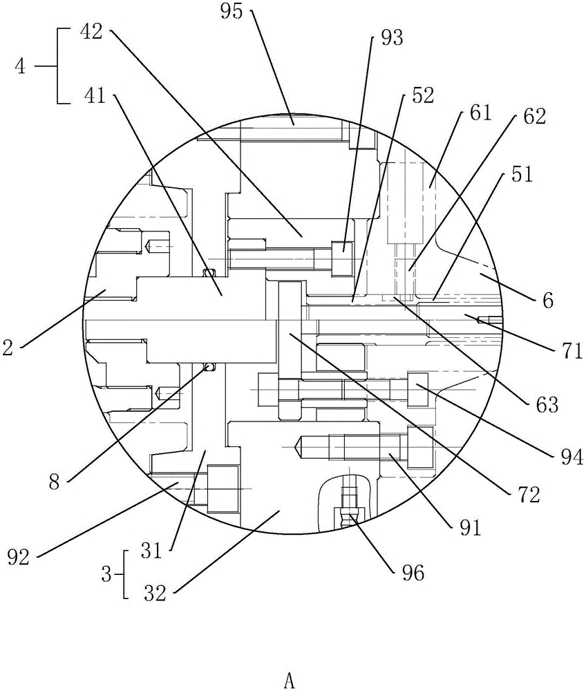
[0032] Embodiment 1: a kind of clamping device, such as Figure 1 to Figure 2 As shown, the main shaft 1 is included, and a cylindrical tie rod 2 is pierced along the inner axis of the main shaft 1 . The axis of the pull rod 2 is set along the horizontal direction. The pull rod 2 is slidably connected with the main shaft 1 , and a cylinder (not shown in the figure) is fixed on the main shaft 1 , the cylinder includes a piston shaft, and the piston shaft is fixedly connected with one end of the pull rod 2 .
[0033] The main shaft 1 is fixedly connected with the connecting disc 3 . The connecting disc 3 is located at the end of the pull rod 2 away from the piston shaft. The connection pad 3 includes a first support portion 31 and a second support portion 32 .
[0034] The first support part 31 is disc-shaped, and has a through hole 311 along its axis, and a first groove 312 and a second groove 313 along its two end surfaces, and the main shaft 1 is embedded. In the first gr...
Embodiment 2
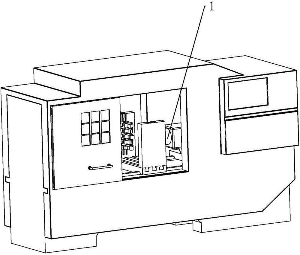
[0041] Embodiment 2: a kind of mind-taking machine, such as image 3 As shown, a clamping device and a frame as described in Embodiment 1 are included. There is a tool holder built in the frame, and a number of knives are placed on the tool holder, which are rotated by the clamping device to make the tool process the parts.
PUM
 Abstract
Description
Claims
Application Information