
Artificial aortic valve support implanted through guide tube and conveying system thereof

An aortic valve and artificial technology, applied in the field of medical devices, can solve the problems of limited surgical implantation, inability to operate, and mitral valve damage, so as to reduce insufficient coronary blood flow and avoid bleeding complications , the effect of less eddy current

Inactive Publication Date: 2013-12-25
徐州亚太科技有限公司
View PDF11 Cites 12 Cited by
  • Summary
  • Abstract
  • Description
  • Claims
  • Application Information

AI Technical Summary

Problems solved by technology

[0004] At present, artificial valve implantation methods include surgical implantation, transcatheter implantation, and percutaneous puncture implantation. However, surgical implantation uses surgical thoracotomy, which involves large trauma and high surgical risks. Surgical operations cannot be performed due to advanced age and symptoms. Patients with psychological barriers to surgical complications, therefore, surgical implantation is more limited
The existing transcatheter implantation of stainless steel valve stents requires balloon expansion to implant the valve stent into the body. Due to balloon expansion, this method is likely to cause the risk of serious complications such as pericardial tamponade and myocardial infarction
However, percutaneous puncture and antegrade implantation, because of the puncture of the interatrial septum, the operation is more complicated, which may cause mitral valve damage, and the mechanical stress acts on the valve stent and surrounding tissues, which may easily cause paravalvular leakage.

Method used


Image

  • Artificial aortic valve support implanted through guide tube and conveying system thereof
  • Artificial aortic valve support implanted through guide tube and conveying system thereof
  • Artificial aortic valve support implanted through guide tube and conveying system thereof

Examples


Embodiment Construction

[0037] The present invention will be further described in detail below in conjunction with the accompanying drawings. It should be understood that the drawings and descriptions provided are only examples of preferred embodiments to illustrate the present invention, and should not be construed as limiting the protection scope of the present invention, which is only limited by the claims.

[0038] 1. Structure description

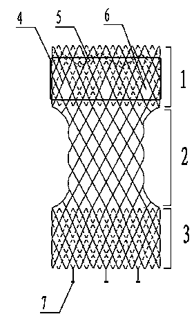
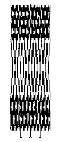
[0039]The artificial aortic valve stent of the present invention comprises a stent and an artificial valve, and the stent is a "dumbbell-shaped" structure made of a highly elastic nickel-titanium alloy wire, including a head 1, a waist 2 and a tail 3, such as figure 1 shown. The head 1 is the proximal end, which is cylindrical and matches the shape of the valve annulus at the root of the aorta; the waist 2 is concave inward, and the mesh is enlarged, corresponding to the opening of the coronary artery; the tail 3 is cylindrical, matching the ascending Corre...


PUM


Abstract

The invention provides an artificial aortic valve support implanted through a guide tube. The artificial aortic valve support comprises a support and an artificial valve. The support is weaved from an elastic-fiber-shaped material, is in a dumbbell structure, and comprises a head, a waist and a tail, and a layer of biocompatible film is covered on an outer surface of the head of the support, and a mounting anchor is mounted at the tail of the support. A conveying system for conveying the support is further provided and comprises an epitheca, an inner core, a loader, a push bar and a fixed head. The mounting anchor at the tail of the support is mounted on the fixed head, and the artificial aortic valve support is conveyed to an inner body through puncturing. The support is close to physiological anatomical structure and is capable of self-expanding separation, and an artificial bio-valve is adopted and is close to the functions of the artificial valve. And the conveying system can be slightly transformed from the conveying system of a heart disease stopper, so that apparatuses used for treating structural heart disease become standard and normal gradually, and meanwhile, resources are also saved and consumption is lowered.

Description

technical field [0001] The invention belongs to the field of medical devices, and in particular relates to an artificial aortic valve stent implanted through a catheter and a delivery system thereof. Background technique [0002] With the advent of an aging society, aortic stenosis will become one of the most common adult valve diseases. Surgical valve replacement is the only effective treatment that improves the patient's symptoms and signs and prolongs life. However, even in developed countries, there are still many patients with severe aortic stenosis who cannot undergo surgical treatment due to advanced age and various comorbidities. At the same time, some patients are reluctant to undergo surgery due to fear of surgical complications. In December 2002, Cribier et al. reported the first case of transcatheter aortic valve replacement in humans. At present, this technology is gradually being used clinically and may become a new treatment method for aortic valve stenosis. ...

Claims


Application Information

Patent Timeline
Patent Type & Authority Applications(China)
IPC IPC(8): A61F2/24
Inventor 刘文修吴言革吴俊龙
Owner 徐州亚太科技有限公司
Learn More