
Metal steel surface treatment device for lining attachment

A surface treatment device and metal technology, which is applied to machine tools, grinding drive devices, and metal processing equipment suitable for grinding workpiece planes. Effect

Active Publication Date: 2022-08-09
湖北华宁防腐技术股份有限公司
View PDF6 Cites 1 Cited by
  • Summary
  • Abstract
  • Description
  • Claims
  • Application Information

AI Technical Summary

Problems solved by technology

[0003] The purpose of the present invention is: for the above-mentioned problem to be solved: when the metal steel is used as a lining, the surface of the metal steel needs to be polished to make the surface of the metal steel smoother. The existing metal steel grinding device can only be single Grinding metal steel, because a large amount of waste and other sundries will be generated when the metal steel is polished, if the waste and sundries are not cleaned up in time, it is very easy to cause damage to the surface of the metal steel, and at the same time, the grinding roller is also easy to operate and damage, so it is necessary The structure of the metal steel grinding device is improved, and at the same time, the invention proposes a metal steel surface treatment device for lining bonding, which is convenient for better grinding of metal steel, and at the same time, it can remove waste and other sundries produced by metal steel grinding to clean up

Method used


Image

  • Metal steel surface treatment device for lining attachment
  • Metal steel surface treatment device for lining attachment
  • Metal steel surface treatment device for lining attachment

Examples


Embodiment Construction

[0025] In order to make the objectives, technical solutions and advantages of the present invention clearer, the present invention will be further described in detail below with reference to the accompanying drawings and embodiments. It should be understood that the specific embodiments described herein are only used to explain the present invention, but not to limit the present invention.

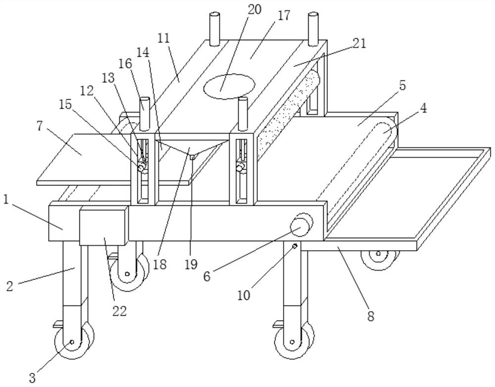
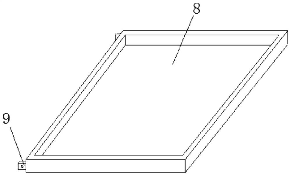
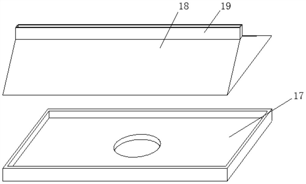
[0026] refer to Figure 1-2 As shown, a metal steel surface treatment device for lining bonding includes a workbench 1, and legs 2 are fixedly connected around the bottom of the workbench 1, and the bottom ends of the legs 2 are provided with universal wheels 3, The steering wheel 3 is provided with a braking device. Both inner ends of the worktable 1 are connected with a transmission roller 4 in rotation, and a conveyor belt 5 is connected to the transmission roller 4. The conveyor belt 5 is a silicone conveyor belt. The right side of the front wall of the worktable 1 A first motor 6 is ...


PUM


Abstract

The metal steel surface treatment device comprises a workbench, supporting legs are fixedly connected to the periphery of the bottom of the workbench, universal wheels are arranged at the bottom ends of the supporting legs, transmission rollers are rotationally connected to the two ends of the inner side of the workbench, and a conveying belt is in transmission connection to the transmission rollers; a first motor is fixedly connected to the right side of the front wall of the workbench, the first motor is connected with the front portion of a right side transmission roller, metal steel is placed on a conveying belt, a waste collecting box is attached to the right wall of a right side supporting leg, positioning plates are fixedly connected to the front portion and the rear portion of the left wall of the waste collecting box correspondingly, and the positioning plates are inserted into the right wall of the right side supporting leg. And pin rods are inserted into the supporting leg on the right side and the positioning plate, so that the metal steel can be better ground, and meanwhile, sundries such as waste materials generated by grinding the metal steel can be cleaned.

Description

technical field [0001] The invention belongs to the technical field of walkers, in particular to a metal steel surface treatment device used for lining bonding. Background technique [0002] When the metal steel is used as a lining, the surface of the metal steel needs to be ground to make the surface of the metal steel smoother. The existing metal steel grinding device can usually only grind the metal steel alone, because a large amount of metal steel will be produced when grinding the metal steel. When the waste and other debris are not cleaned in time, it is easy to cause damage to the surface of the metal steel, and at the same time, it is easy to damage the grinding roller. Therefore, it is necessary to improve the structure of the metal steel grinding device. At the same time, the present invention proposes The utility model relates to a metal steel surface treatment device used for lining bonding, which is convenient for better grinding of metal steel, and at the same...

Claims


Application Information

Patent Timeline
Patent Type & Authority Applications(China)
IPC IPC(8): B24B7/06B24B7/10B24B41/04B24B47/12B24B47/22B24B51/00B24B55/06B24B55/12
CPCB24B7/06B24B7/10B24B41/04B24B47/12B24B47/22B24B55/06B24B55/12B24B51/00Y02P70/10
Inventor 蒋金中蒋俊王砚林肖良炎何伟兰希园
Owner 湖北华宁防腐技术股份有限公司
Learn More