
Low Pressure Polishing Method and Apparatus

a technology of surface polishing and low pressure, which is applied in the direction of brushes, applications, other manufacturing equipment/tools, etc., can solve the problems of floor cleaning machines that are used, minute particles of concrete to break away, and the surface of concrete floor deterioration tendency of floor cleaning machines, etc., to achieve enhanced surface finish quality, improved surface finish, and improved grit density

Active Publication Date: 2009-09-03
DIAMABRUSH
View PDF6 Cites 34 Cited by
  • Summary
  • Abstract
  • Description
  • Claims
  • Application Information

AI Technical Summary

Benefits of technology

[0006]It will be desirable to forego the aforementioned costly steps by providing an improved cleaning and honing brush that works as an attachment to an ordinary cleaning machine, such as a Tennant or Advance brand scrubber machine. It would be desirable to provide an improved cleaning and honing brush that operates under low pressure, does not require an independent power source, continuously exposes new abrasive material during the cleaning process and has interchangeable replaceable polymer brush strips that can be easily removed and replaced with replacement polymer brush strips.
[0009]It will be desirable to provide an improved polishing system that can be used in connection with a traditional automatic flooring machine wherein a series of diamond embedded polymer strips are used with a rotary disc. The rotary disc bearing the polymer strips can also be used for cleaning the surface of the concrete as well as providing a polishing aspect during the process of cleaning. The floor cleaning process employs a rotary disc having polymer strips with greater grit density so as to provide an improved surface finish. The process is repeated routinely whereby at each cycle the polymer strips are changed out to have finer grit size so as to continuously enhance the surface finish quality. The aforementioned process is accomplished while cleaning the floor during low speed and low pressure conditions. Said process can be used with floors other than concrete floors.

Problems solved by technology

Typically these floor cleaning machines have a tendency of progressively deteriorating the surface of the concrete floor.
This is caused by the bristles extending into the naturally occurring crevices in the concrete floor thus causing minute particles of the concrete to break away.
Typically the flooring machines that are used on a routine basis sit idle as they have a limited purpose, which is to clean the floor.
Accordingly, because these machines have limited purposes, they are seldom used, thus creating inefficiencies for a business.
However, the loosened wax tends to gum up the surface of the pad making removal very difficult.

Method used


Image

  • Low Pressure Polishing Method and Apparatus
  • Low Pressure Polishing Method and Apparatus
  • Low Pressure Polishing Method and Apparatus

Examples


Embodiment Construction

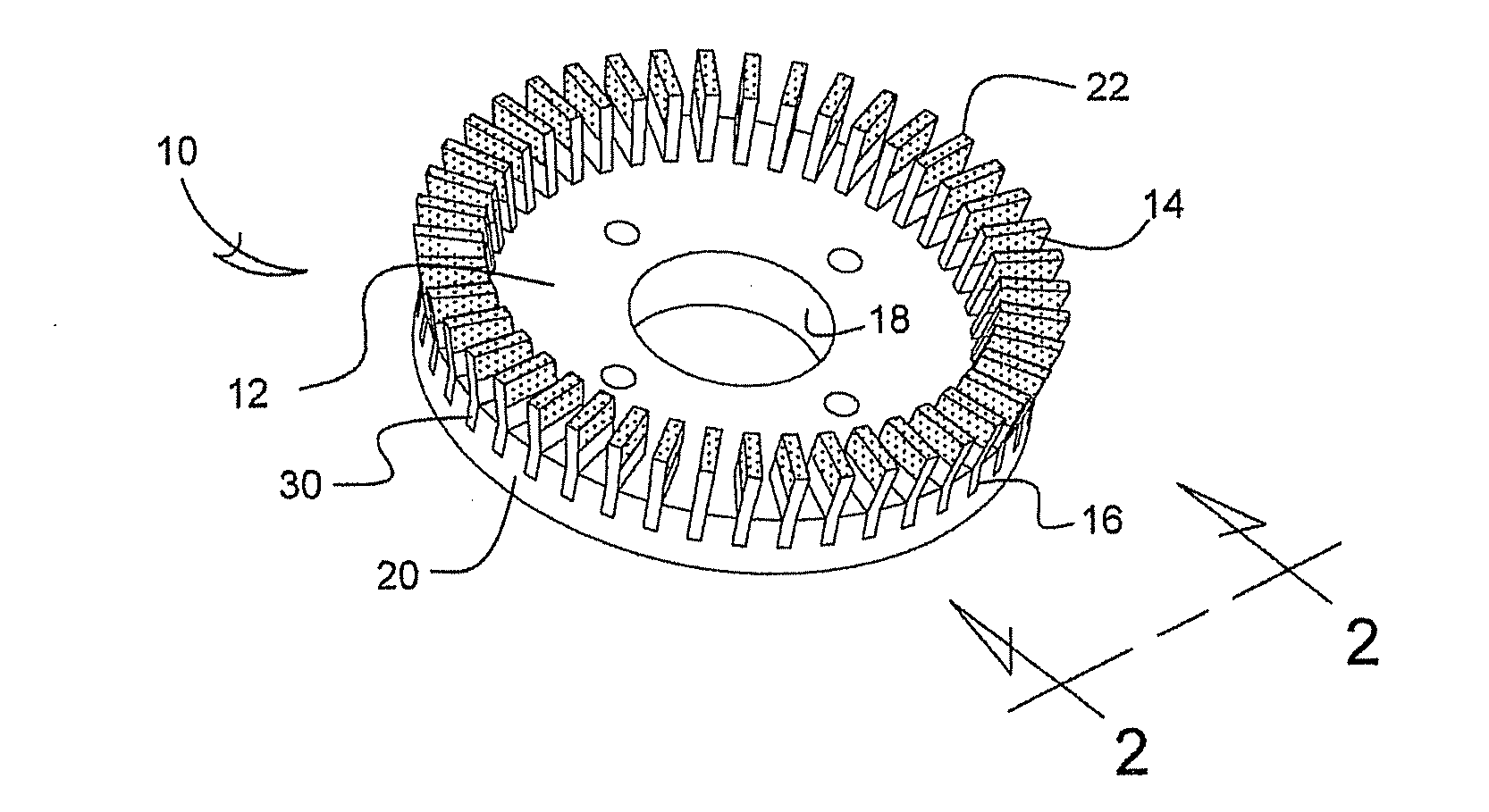
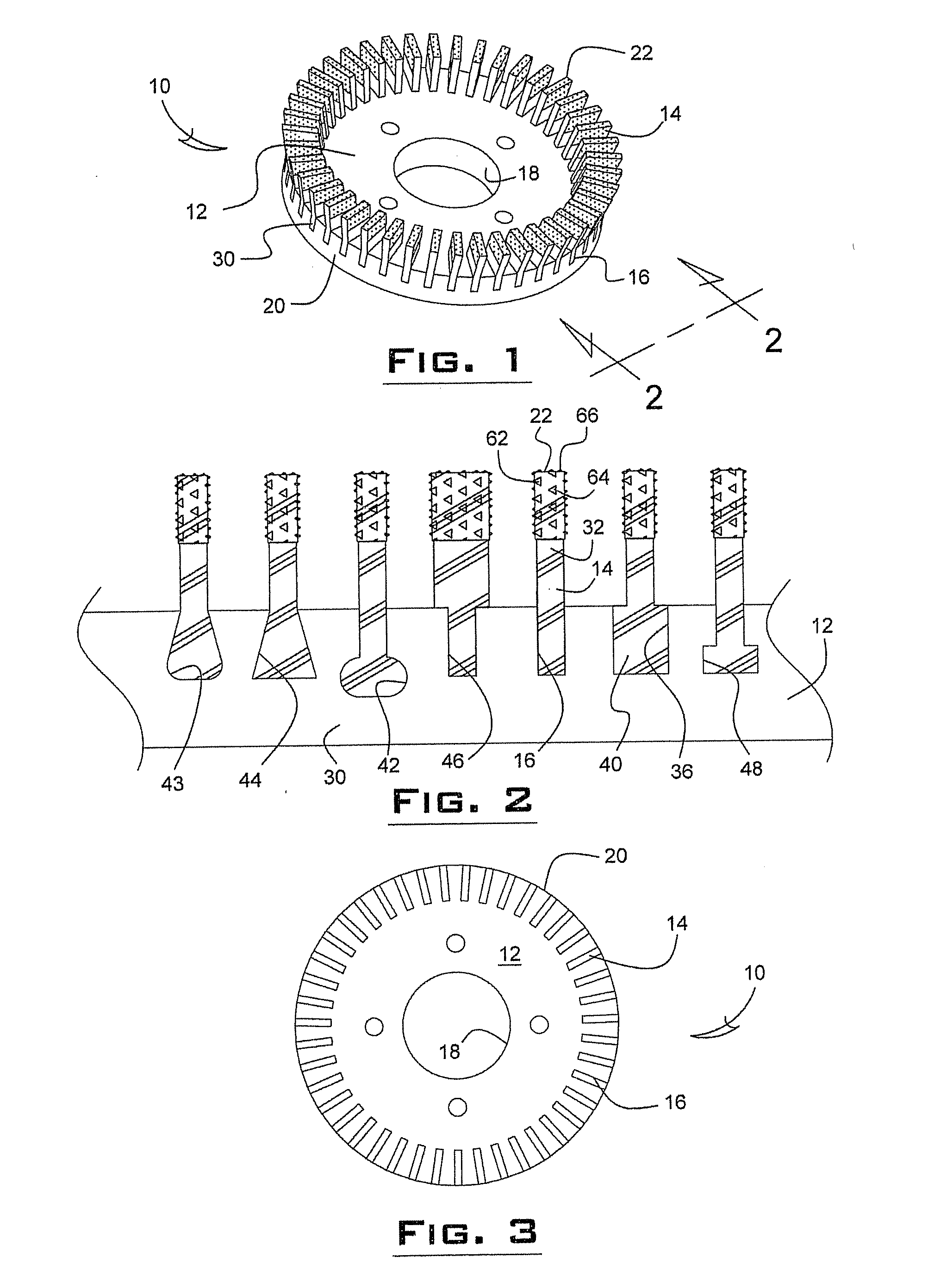
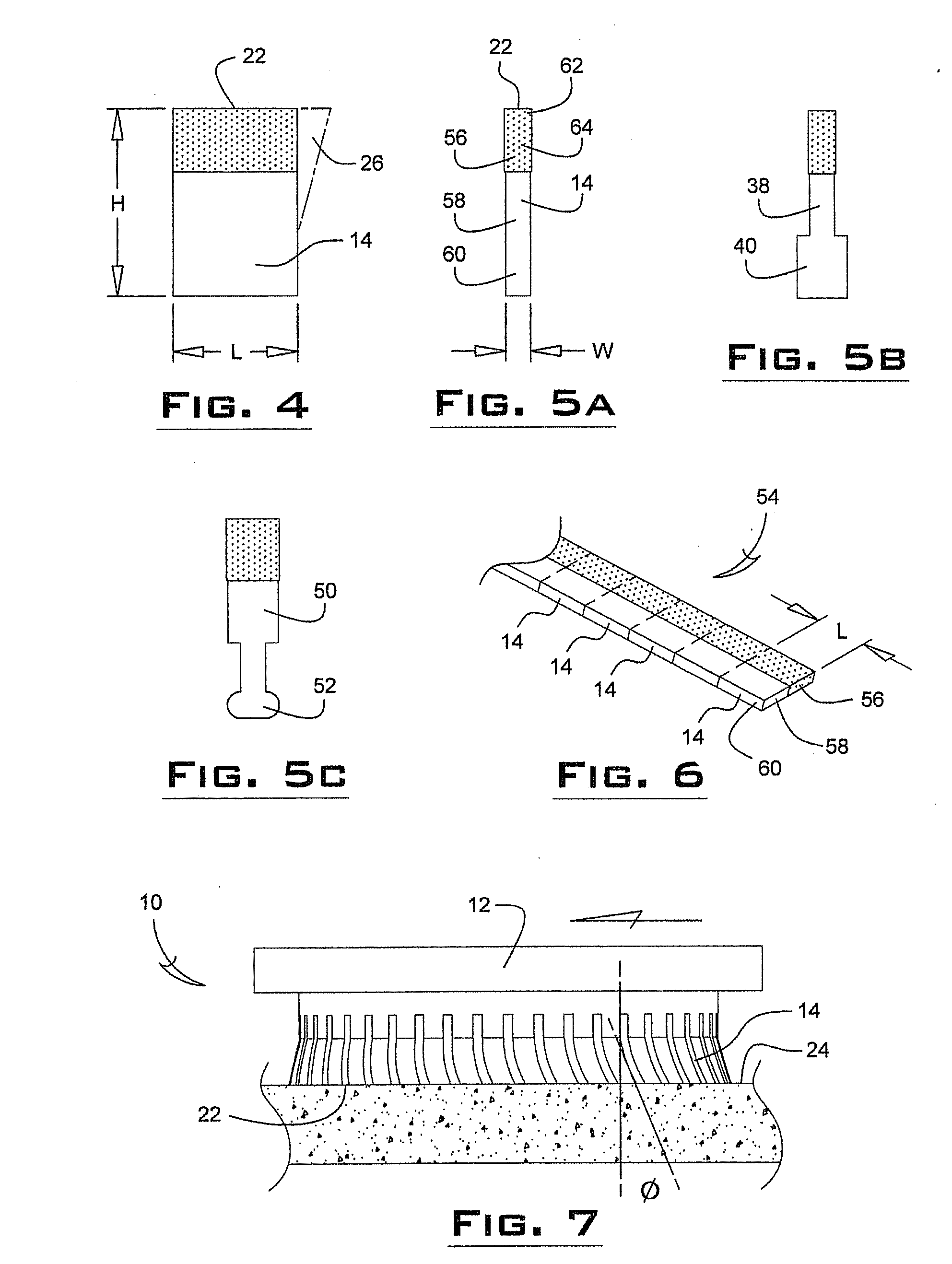
[0045]An improved polishing device 10 includes a circular-shaped pad 12 having a plurality of polymer strips 14 retained within slots 16 of the pad 12. The pad 12 has an internal diameter 18 that is operable to receive the drive shaft of a rotary machine, including an automatic flooring machine (not shown). The flooring machine can be of the type that traditionally cleans concrete floors as is well known in the art. The drive shaft may impart motion to the pad 12 at approximately 125 to 200 rpm's while applying approximately 150 to 200 lbs. of total pad pressure. The device 10 can be used in low speed low pressure conditions. However, it is possible to utilize the various devices disclosed herein in higher speed applications where higher pressures are encountered. For example, if desired, the present invention could be used with machines operating in the 125-1500 RPM range and at head pressures in the 50-800 PSI range.

[0046]It will be appreciated that several polishing devices 10 ca...


PUM

PropertyMeasurementUnit
Shapeaaaaaaaaaa
Abrasiveaaaaaaaaaa

Abstract

An improved low pressure low speed concrete polishing apparatus and method of cleaning and polishing a floor is used with a conventional rotary flooring machine. A polishing pad has interchangeable polymer strips that are slideably received within the housing of the pad. The polymer strips have an abrasive material embedded therein which collectively work to polish the floor while cleaning the floor during normal low speed floor cleaning conditions.

Description

CROSS REFERENCE TO RELATED APPLICATIONS[0001]This application claims priority to U.S. Provisional Patent Application No. 61 / 095,077, filed on Sep. 8, 2008, entitled LOW PRESSURE POLISHING METHOD AND APPARATUS; and is a continuation-in-part of related application U.S. application Ser. No. 11 / 660,623 filed Feb. 16, 2007, entitled ABRASIVE CLEANING DEVICE; and related continuation-in-part Issued Pat. No. 7,081,047 (application Ser. No. 11 / 042,698 filed Jan. 25, 2005) entitled BRISTLE BRUSH FOR CONCRETE SANDING, the disclosures of which are incorporated by reference in their entirety.TECHNICAL FIELD[0002]This invention relates to a method of polishing surfaces and an apparatus for polishing or modifying floor surfaces.BACKGROUND AND SUMMARY OF INVENTION[0003]Concrete is traditionally used for floors in both residential and commercial applications in view of its robustness and economic benefits. Depending upon the circumstances, the concrete may be left unfinished, partially finished or ...

Claims


Application Information

Patent Timeline
IPC IPC(8): B24B7/00
CPCA46B13/008A46B13/02A46B2200/3093A46D1/00A46D1/0207B24D13/16A46D1/0269B24B1/00B24B3/00B24B7/18B24D13/06A46D1/0238
Inventor PALUSHAJ, SIMON
Owner DIAMABRUSH
Learn More