

Method for determining a low cylinder pressure condition for a gas chromatograph
a gas chromatograph and low cylinder pressure technology, applied in the field of gas chromatography, can solve the problems of low carrier condition to be sensed, too late, and compromise of analysis underway
- Summary
- Abstract
- Description
- Claims
- Application Information
AI Technical Summary
Benefits of technology
Problems solved by technology
Method used
Image

Examples
Embodiment Construction
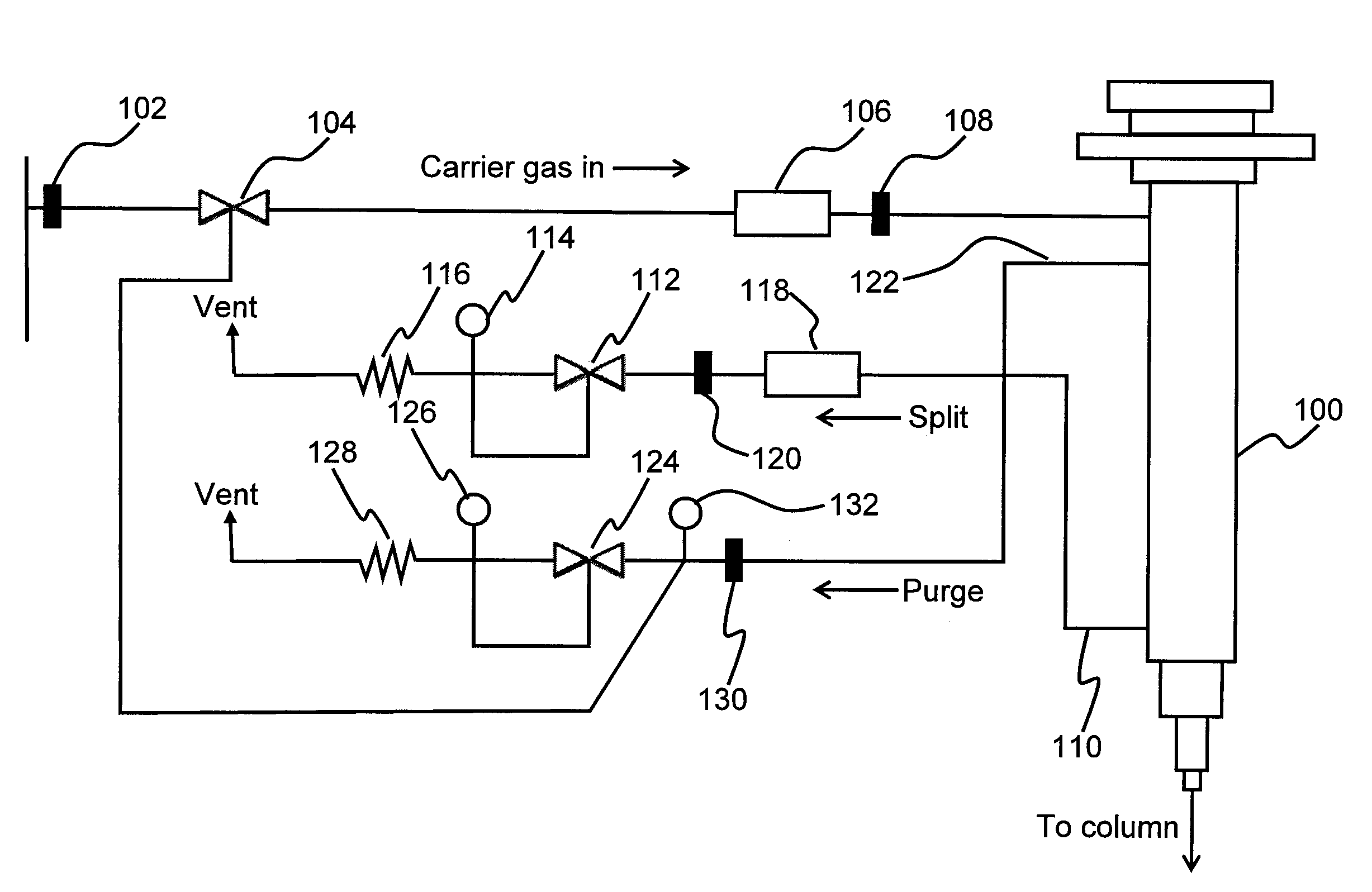
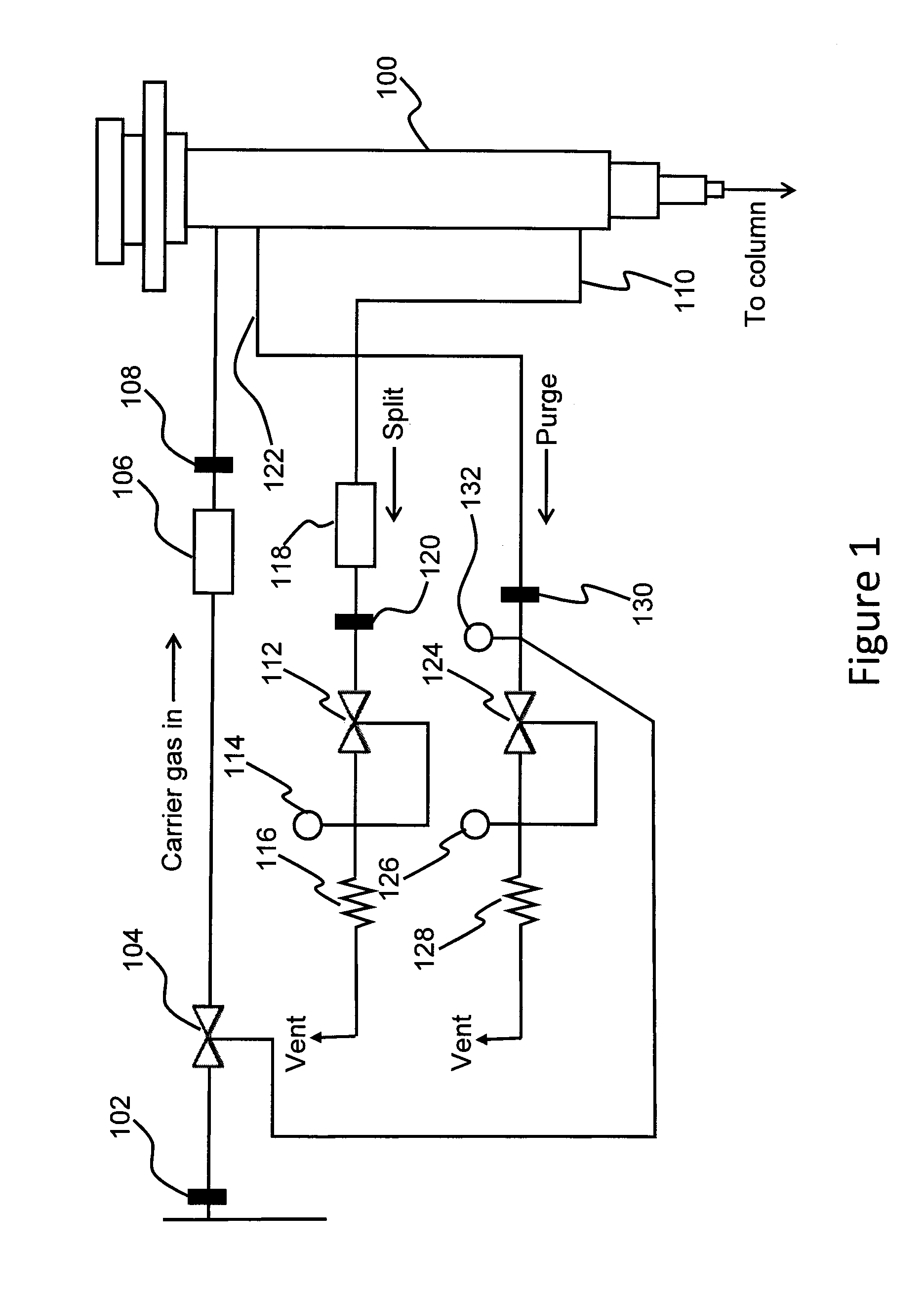
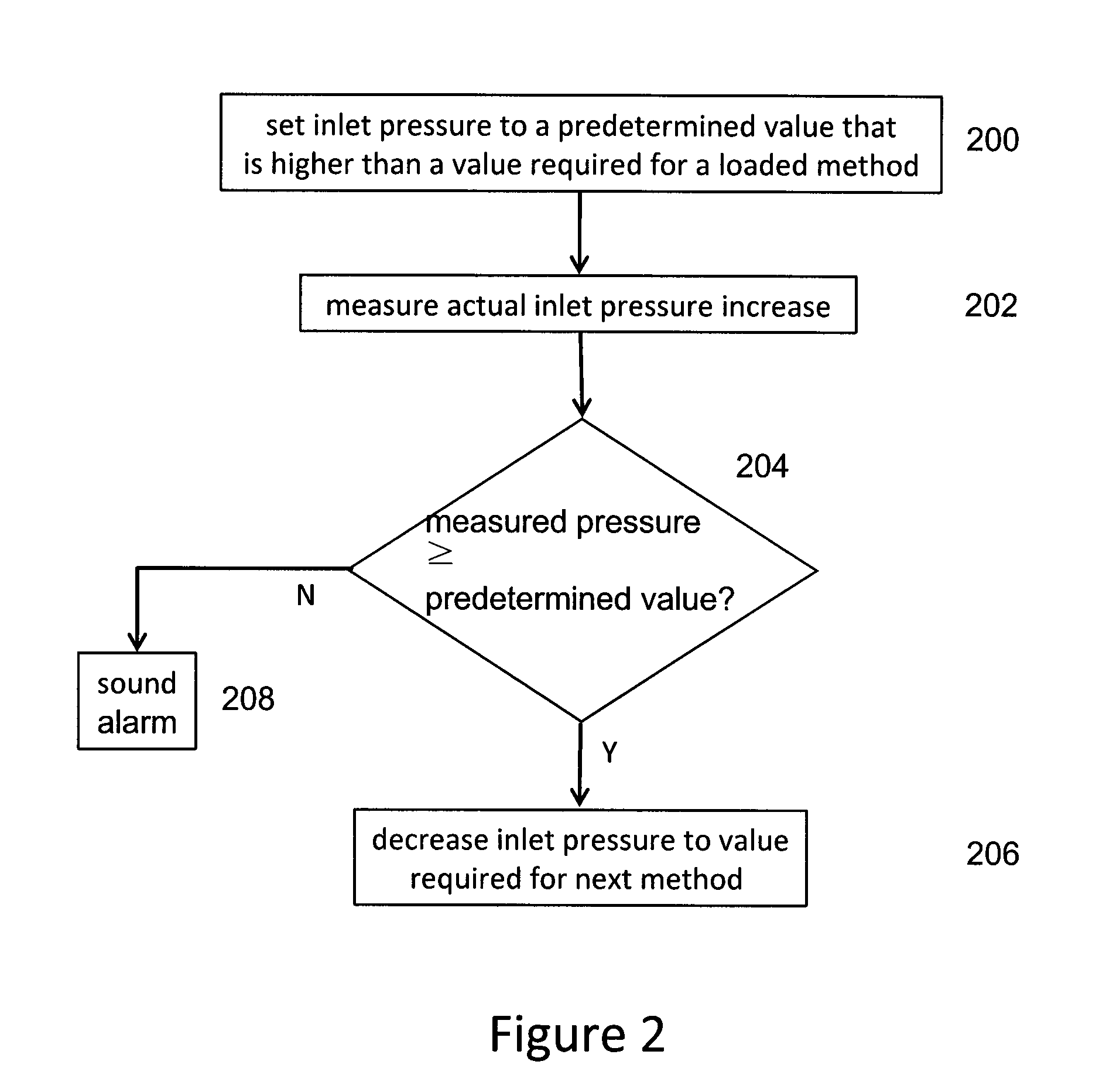
[0007]According to an aspect of the invention there is provided a method for determining a low cylinder pressure condition of a gas chromatograph, the method comprising: providing gas from the cylinder to an inlet of the gas chromatograph, the gas being provided at a predetermined inlet pressure during a first period of time; during a second period of time, increasing the inlet pressure of the gas that is being provided from the cylinder; determining if the inlet pressure increases to at least a predetermined check value during the second period of time; and, if it is determined that the inlet pressure of the gas does not increase to at least the predetermined check value, providing an indication of a low cylinder pressure condition.
[0008]According to an aspect of the invention there is provided a method for determining a low cylinder pressure condition of a gas chromatograph, the method comprising: providing a supply of gas from the cylinder to a component of the gas chromatograph,...
PUM
| Property | Measurement | Unit |
|---|---|---|
| flow rate | aaaaa | aaaaa |
| flow rate | aaaaa | aaaaa |
| cylinder pressure | aaaaa | aaaaa |
Abstract
Description
Claims
Application Information