
Desalination system and process using atmospheric pressure as renewable energy

a technology of renewable energy and desalination system, which is applied in water conservation, energy-based wastewater treatment, machines/engines, etc., can solve the problems of large amount of heat to cause evaporation, large amount of energy, and inability to meet the needs of wide-scale us

Inactive Publication Date: 2015-12-31
PIERRE MARVIN W
View PDF3 Cites 0 Cited by
  • Summary
  • Abstract
  • Description
  • Claims
  • Application Information

AI Technical Summary

Benefits of technology

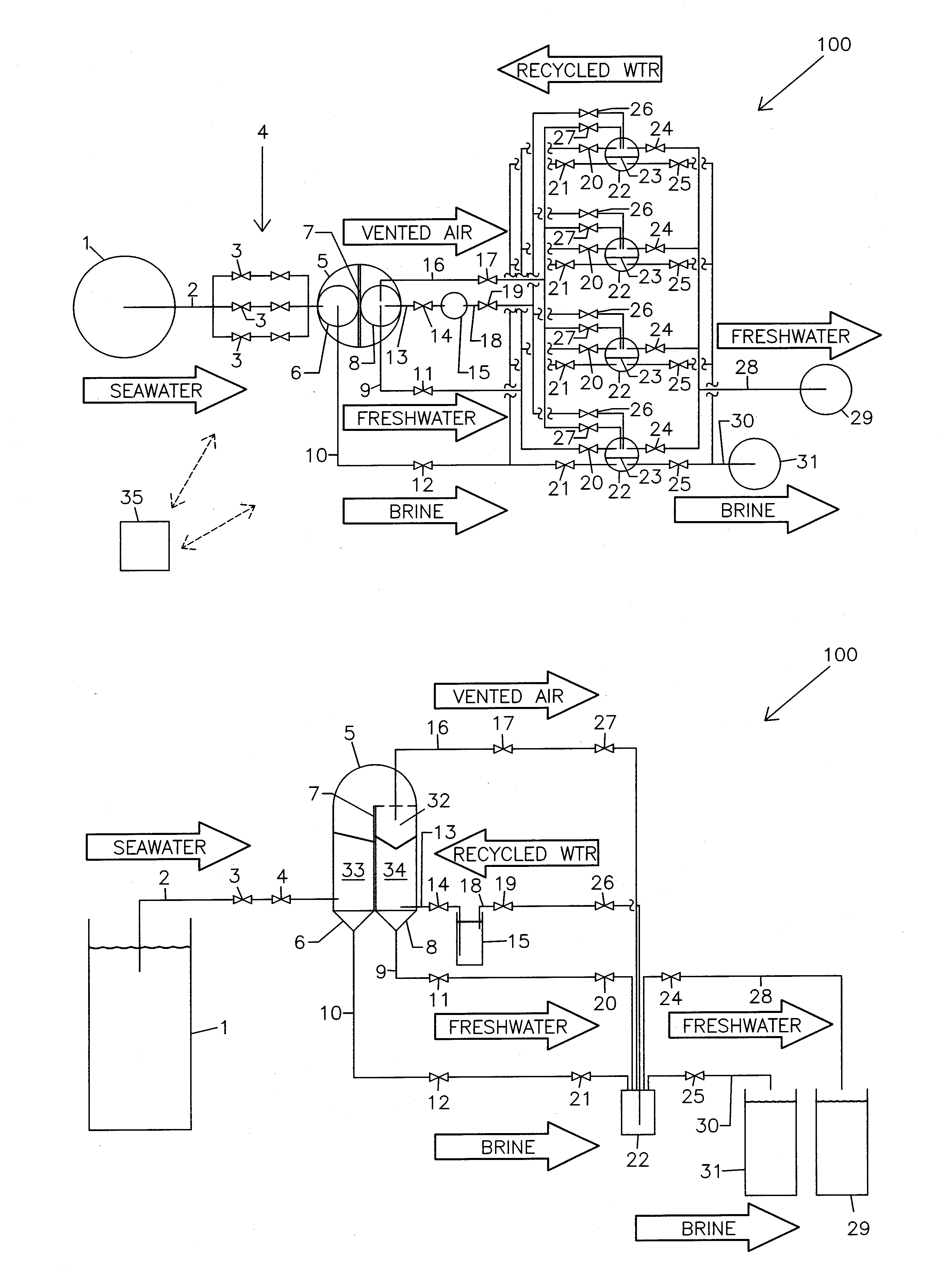
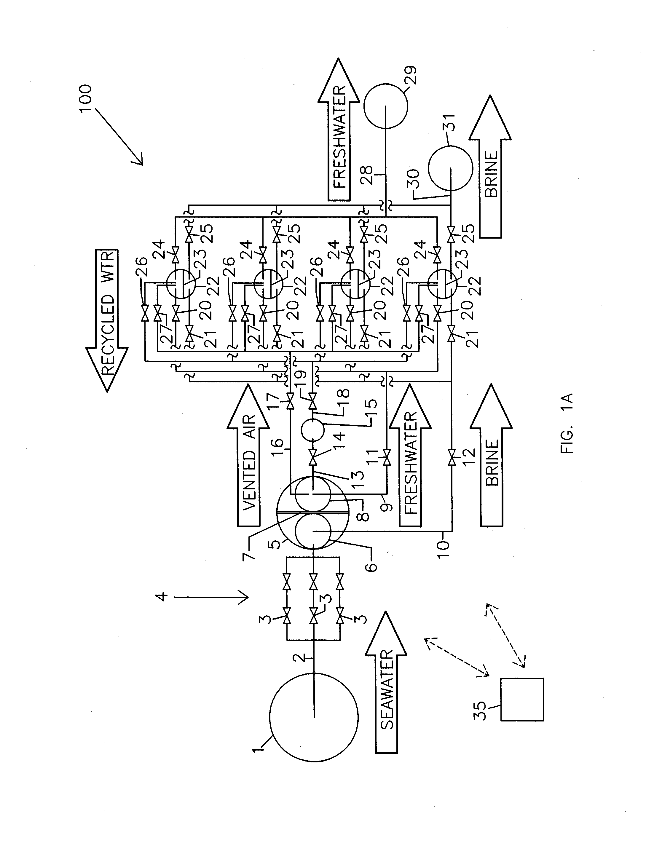
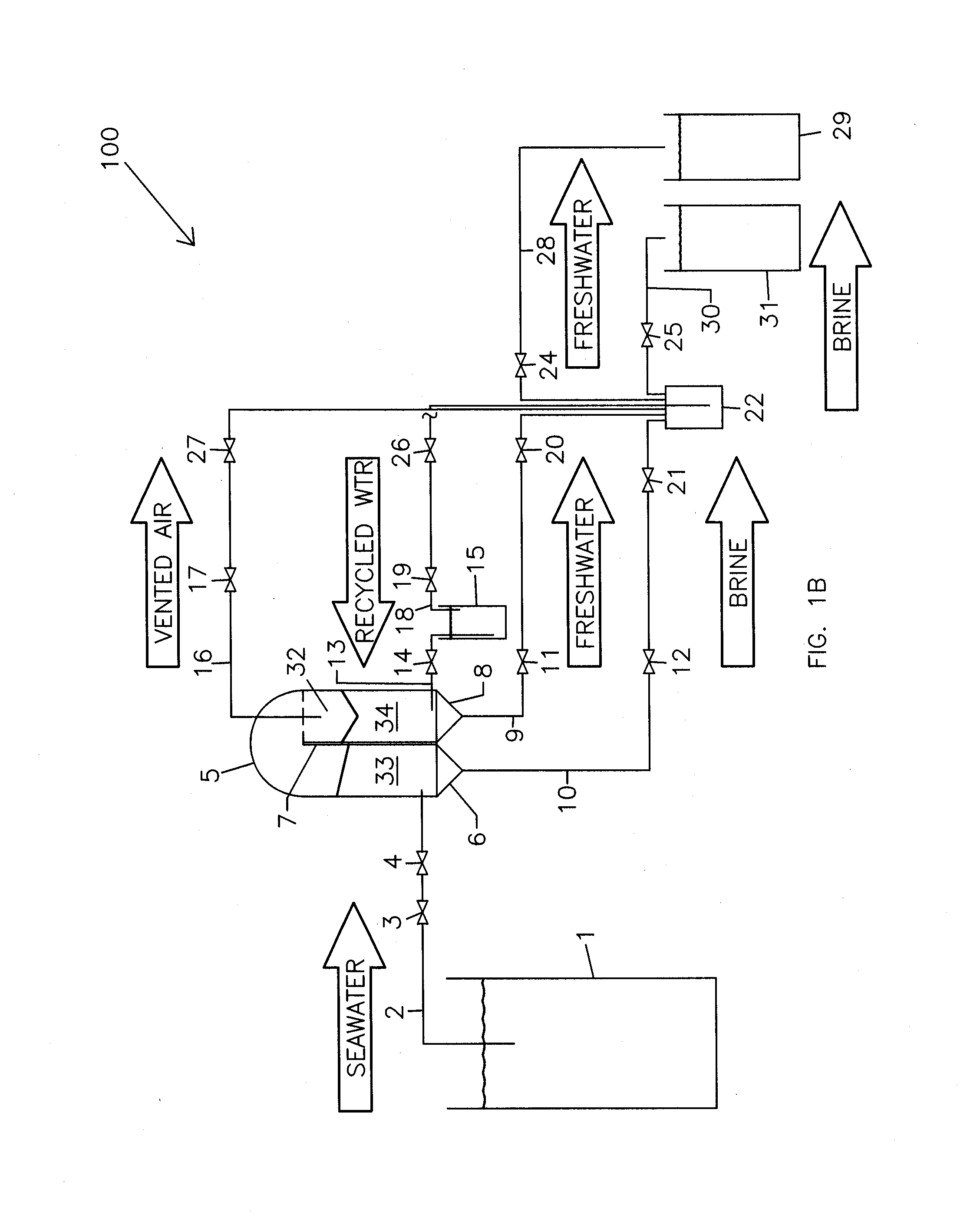
The present patent describes a system and process for desalination of saltwater using a specialized pump to handle low pressure conditions. The system takes advantage of the phase change cycle associated with cavitation on the suction side of the pump to efficiently desalinate the water. The process involves enclosing an upstream and downstream containment section, creating initial vapor inside the containment vessel, using atmospheric pressure to drive recycled water into the containment section, and then using a heat exchanger to transfer heat released by condensation and vaporization from one side to the other. The system also includes a pump system to pump both saltwater and freshwater, a vent to release pressure, and valves to control friction and maintain desired water levels. The technical effect of the system is to provide an efficient and effective means for desalination of saltwater.

Problems solved by technology

Processes in place for converting seawater to freshwater are still economically unattractive for wide spread use.
Both of these techniques require substantial amounts of energy to accomplish the desalination process, which is a significant economical barrier for common use.
For thermal techniques, large amounts of heat must be utilized to cause evaporation.

Method used


Image

  • Desalination system and process using atmospheric pressure as renewable energy
  • Desalination system and process using atmospheric pressure as renewable energy
  • Desalination system and process using atmospheric pressure as renewable energy

Examples


Embodiment Construction

[0025]The disclosure and the various features and advantageous details thereof are explained more fully with reference to the non-limiting examples that are described and / or illustrated in the accompanying drawings and detailed in the following description. It should be noted that the features illustrated in the drawings are not necessarily drawn to scale, and features of one example may be employed with other examples as the skilled artisan would recognize, even if not explicitly stated herein. Descriptions of well-known components and processing techniques may be omitted so as to not unnecessarily obscure the principles of the disclosure. The examples used herein are intended merely to facilitate an understanding of ways in which the disclosure may be practiced and to further enable those of skill in the art to practice the examples of the disclosure. Accordingly, the examples herein should not be construed as limiting the scope of the disclosure. Moreover, it is noted that like r...


PUM

PropertyMeasurementUnit
Energyaaaaaaaaaa
Energyaaaaaaaaaa
Energyaaaaaaaaaa

Abstract

A system configured according to principles of the disclosure and process performed according to principles of the disclosure exploit a phase change cycle associated with cavitation on the suction side of (or inside) a pump to separate salt and / or impurities from water with exceptional efficiency. The exploitation involves enhancing the well-known process of cavitation by providing a large container in which the phase changes can occur safely, creating initial vapor inside the large container to start and perpetuate the process, using atmospheric pressure to drive water or recycled water into (or downstream of) the large container to force vapor compression and condensation inside the large container, and then providing a heat exchanger inside the large container to transfer heat released by condensation and vapor compression from its freshwater side to its vaporization side. A specialized pump configured to handle very low pressure conditions on its suction side more effectively and efficiently than other pumps may be used. The system and process may produce freshwater at about 0.01 gpm to about 1,080 gpm, or more.

Description

CROSS REFERENCE TO RELATED APPLICATIONS[0001]This application claims benefit and priority from International Application No. PCT / US2014 / 047943, filed Jul. 24, 2014, which is based on and claims priority to U.S. Provisional Patent Application No. 61 / 858,432, filed Jul. 25, 2013, the disclosures of which would be incorporated therein by reference in their entireties. This application also claims the benefit as a continuation-in-part of U.S. patent application Ser. No. 13 / 434,516, filed Mar. 29, 2012, which is based on and claims priority to U.S. Provisional Patent Applications, Nos. 61 / 486,596, 61 / 608,428, and 61 / 613,728, filed May 16, 2011, Mar. 8, 2012, and Mar. 21, 2012, respectively, the disclosures of which are also incorporated herein by reference in their entireties.BACKGROUND[0002]1. Field of the Disclosure[0003]This present disclosure relates to a system and method for water purification and, more particularly, to a system and method for desalinating salt water and may includ...

Claims


Application Information

Patent Timeline
IPC IPC(8): C02F1/06B01D3/00F04B9/06B01D5/00C01B5/00B01D1/14B01D3/34
CPCB01D3/06C02F2209/03C02F1/048F04B15/00Y10S203/17Y10S203/08Y02P70/34Y02W10/37C02F1/06B01D1/14B01D3/007B01D3/346B01D5/006C01B5/00F04B9/06C02F2103/08C02F1/008C02F2209/006B01D1/28B01D1/2881B01D1/2887B01D1/289Y02A20/128C02F2209/40C02F2209/02B01D5/0039Y02A20/124Y02P70/10
Inventor PIERRE, MARVIN W.
Owner PIERRE MARVIN W
Learn More