Two-Times-Two Tank Process and System

a technology of thermal hydrolysis and tank process, which is applied in the direction of biological water/sewage treatment, biological sludge treatment, waste based fuel, etc., can solve the problems of loss of thermal energy, and more heat loss to the vacuum system, so as to reduce the consumption of steam and reduce the cost of operation. , the effect of reducing the amount of was

Pending Publication Date: 2022-01-20
CAMBI TECH AS
View PDF5 Cites 0 Cited by
  • Summary
  • Abstract
  • Description
  • Claims
  • Application Information

AI Technical Summary

Benefits of technology

[0023]It is therefore an objective of the present invention to provide processes and plants that, in the context of processes involving THP and steam explosion, enables optimization of steam consumption by achieving a lower steam consumption compared to the processes of the prior art
[0024]It is yet another object of the present invention to provide processes and plants that, in the context of processes involving THP and steam explosion, enables optimization of steam consumption by achieving a lower steam consumption compared to the processes of the prior art, and which are simple and easy to integrate into existing wastewater treatment plants by retrofitting.
[0025]Finally, it is an objective of the present invention by using the methods of the present invention as an add-on by retrofitting to any thermal hydrolysis process with a cold feed and a warm discharged liquid. Thus, the methods of the present invention could be combined with the processes described in e.g. WO / 2011 / 006854 and WO / 2014 / 123426 and other similar thermal hydrolysis processes with the aim to improve heat recovery and reduce overall energy consumption.

Problems solved by technology

Furthermore, the pulper is normally maintained at ambient pressure, wherefore feed temperatures higher than approximately 23-25 C, the specific temperature depending on the specific heat losses of the specific process, will result in boiling in the pulper and loss of thermal energy.
Alternatively, both the pulper and flashtank is maintained at higher than ambient pressure to prevent boiling in the pulper, but this will also result in loss of thermal energy due to higher temperatures in the treated substrate discharged from the THP.
As the later systems are, however, known to be prone to leakage, wear and tear, and given the presence of H2S and thiols, the former method relying on flashsteam injection below liquid level in the pulpers is preferred.
With lower total pressure in the pre-heating vessel, more flash steam is recovered from the connected flashtank, while more heat is lost to the vacuum system since the ratio between steam and non-condensable gases increases.

Method used


Image

  • Two-Times-Two Tank Process and System
  • Two-Times-Two Tank Process and System
  • Two-Times-Two Tank Process and System

Examples


example 1

[0134]A plant according to a preferred embodiment of the present invention comprises at least two vacuum vessels one upstream the THP (pulper 1(a)) and, one downstream the THP (flashtank 2(b)). The two vessels are connected with a pipe from top of flashtank 2(b) through lances distributed in piper 1(a). A vacuum compressor (c) e.g. liquid ring compressor, connected to the headspace of the pulper 1(a) will produce a vacuum in the head space of the piper. The work produced by the vacuum compressor will be made on the gases that are not condensed in the pulper 1(a) and the subsequent condenser cooler (d). Flash steam from flashtank 2(b) will be pulled through the pulper 1(a) and condense as it enters the liquid phase in piper 1(a) through the flash steam lances(s). The pulper 1 steam partial pressure will be around 0.2 bar, which means boiling point of approx. 60° C., while the total pressure might be somewhat higher due to the presence of other non-condensable gases. Some steam will f...

example 2

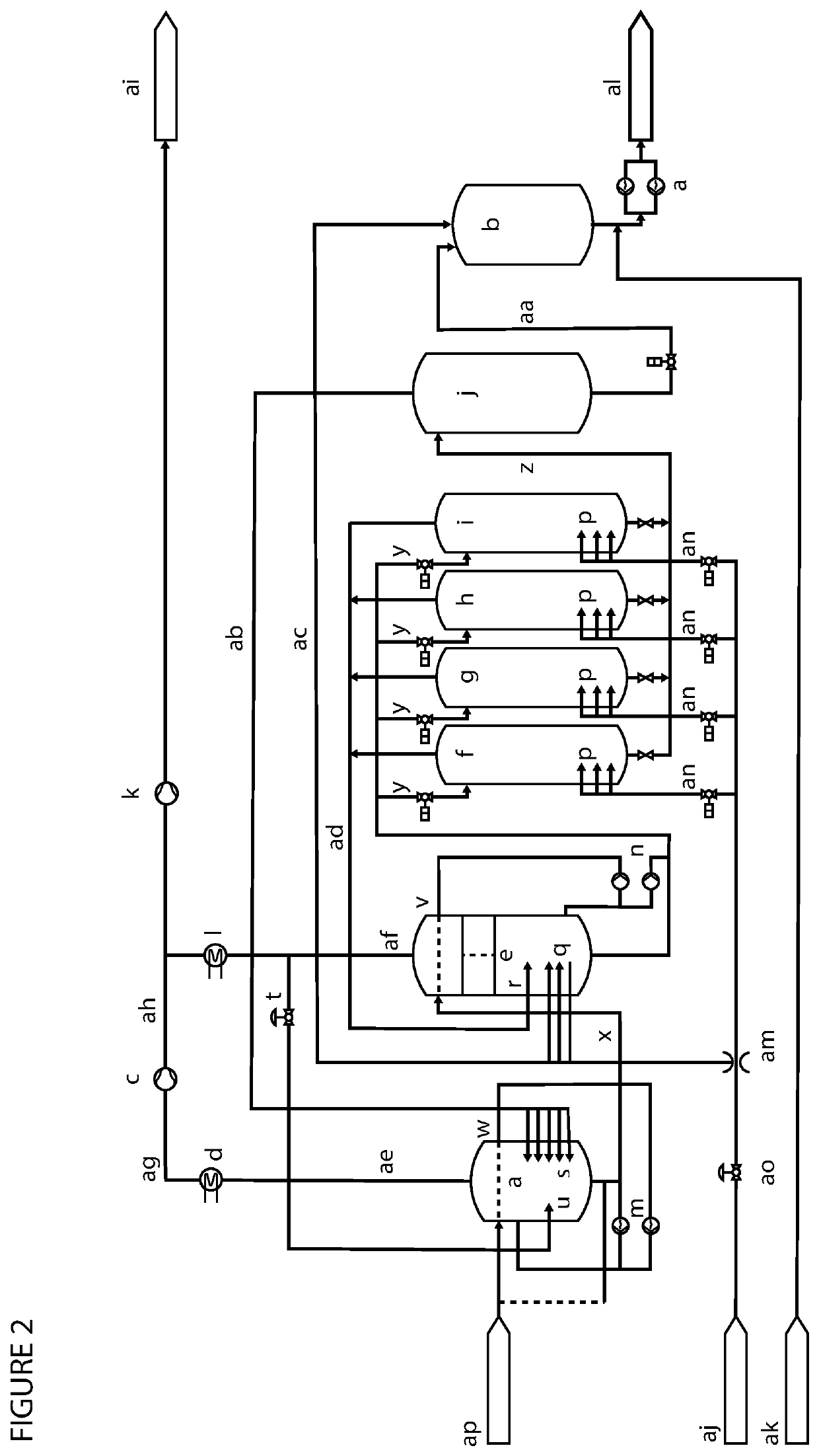
[0144]In the present example, the additional pulper and flashtank required in a method or plant according to the present invention will be referred to as pulper a and flashtank b, respectively. A THP plant with the invention will also include pulper e and flashtank j that are similar to vessels in existing THP plants. The main process flows are shown in the figure below.

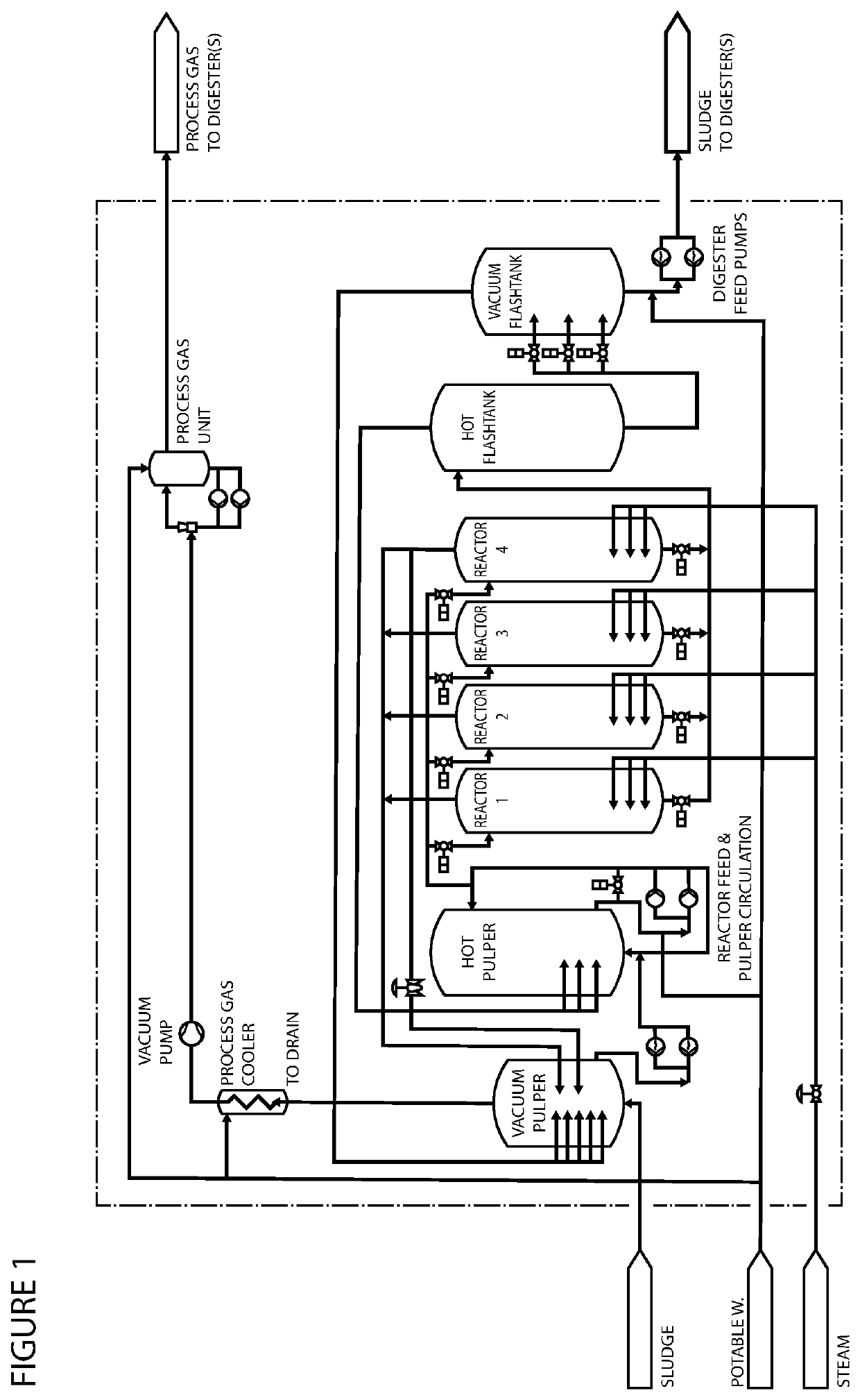
[0145]FIGS. 1 and 2 show two different embodiments of a system according to the present invention.

[0146]Pulper a

[0147]All lines for ventilation of non-condensable gases from pulper e will go to below liquid level in pulper a. Pulper a will be fitted with a vacuum pump and be at the lowest pressure in the system. The temperature and pressure in the headspace of pulper a will be measured to calculate the partial pressure of steam and other gases. The goal is to control the total pressure in pulper a to prevent the substrate from boiling while maintaining the concentration of non-condensable gases at a low level. There ...

example 3

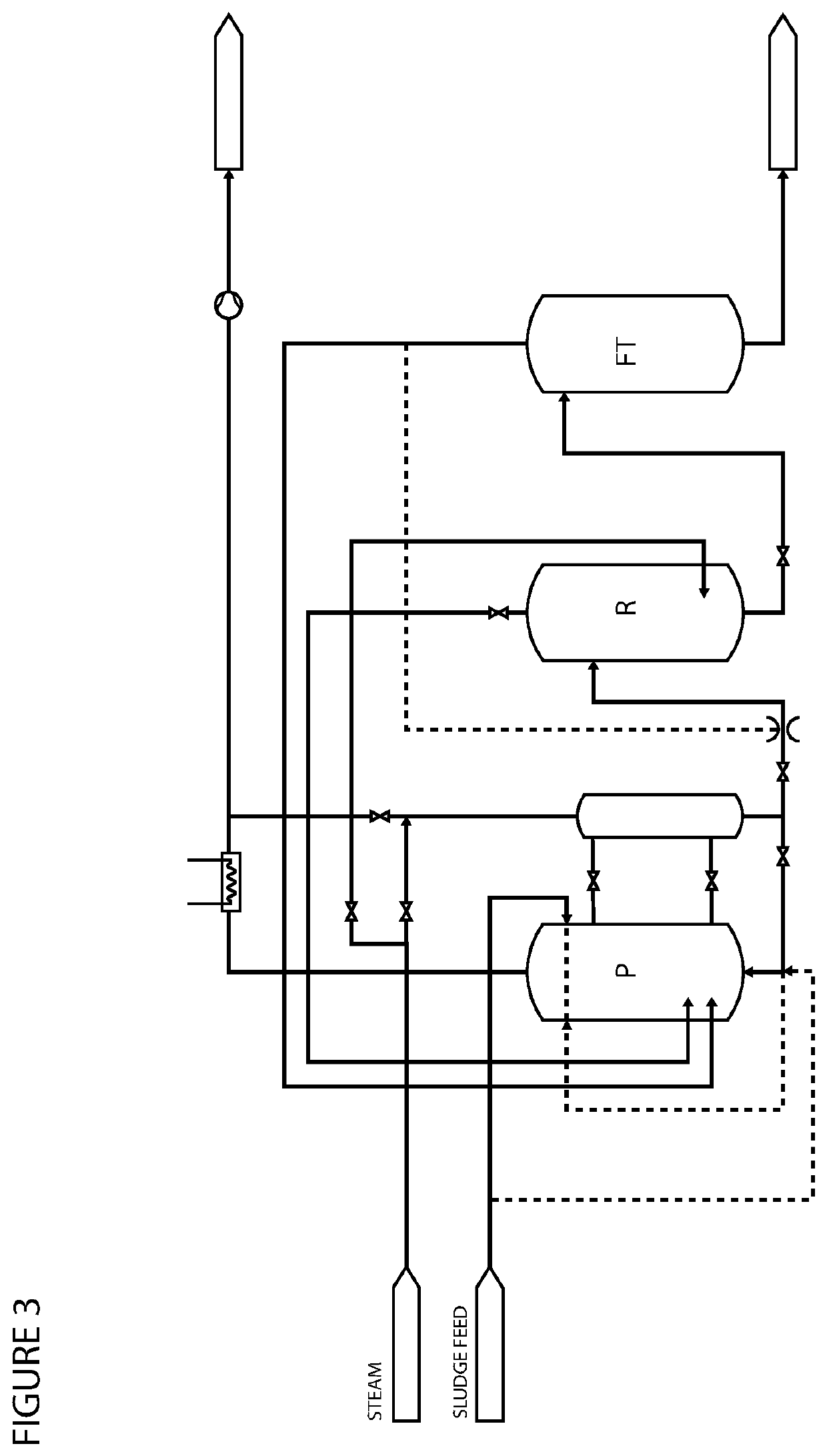
[0162]In most jurisdictions around the world, a plant or system comprising pressure vessels needs to be inspected on a regular basis, e.g. on annual basis, as part of the certification of the industrial facilities (e.g. a plant or system according to the present invention) comprising pressure vessels. National or regional regulations may regulate the specific inspection frequency required. As a consequence of the time required for such inspections, a plant according to the present invention as described in examples 1 and 2 will be subjected to certain down-time periods leading to a reduced capability to process liquid substrates. In such situations the stable plant operation of a plant or a system according to either of examples 1 or 2 above can be achieved by a) implementing additional elements / features allowing for the safe isolation of each of the one or more pulper and / or flashtank units, thereby enabling a reduced operation mode allowing for individual inspection of each pulper...


PUM

PropertyMeasurementUnit
temperaturesaaaaaaaaaa

Abstract

A method and plant for hydrolysis of a liquid substrate, having a dry solids content of between 2 and 30%, to be used in an anaerobic fermentation, digestion or another process aimed at producing or extracting methane or other valuable substances, which method and plant relies on the use of vacuum and several pulpers and one or several flashtanks in series for step-wise pre-heating and pressure reduction, respectively.

Description

FIELD OF THE INVENTION[0001]The present invention relates to methods and plants employing Thermal Hydrolysis Processes (THP), which make use of pulpers and flashtanks for pre-heating and, pressure reduction, respectively. The present invention also relates to methods for retrofitting existing plants employing Thermal Hydrolysis Processes (THP).BACKGROUND OF THE INVENTION[0002]A Thermal Hydrolysis Process (THP) is a process where a wet or moist material is treated at elevated temperatures, typically between 140 to 220 C, which may be followed by a steam explosion by a rapid reduction in the partial pressure of steam.[0003]THP followed by steam explosion is mostly used for pre-treatment of biosolids prior to anaerobic digestion. However, other materials can be pre-treated in the same manner, following which they can be further processed via a wide range of other down-stream processes.[0004]Thermal Hydrolysis Processes (THP) may be designed for either batch or continuous mode. The meth...

Claims


Application Information

Patent Timeline
Patent Type & Authority Applications(United States)
IPC IPC(8): C02F11/04C02F11/18C02F3/28
CPCC02F11/04C02F3/2866C02F11/18C12P5/023C12P2201/00Y02E50/30Y02P20/582
Inventor HOLTE, HANS RASMUSLILLEBO, ANDREAS HELLAND
Owner CAMBI TECH AS
Why Eureka
Try Eureka