A screw barrel cooling device

A cooling device and screw barrel technology, applied in the field of extruders, can solve the problems of seeping out of the barrel and liquid easily infiltrating between two flanges, etc., and achieve the effect of uniform temperature and uniform cooling

Active Publication Date: 2018-09-25
镇江越升智能装备制造有限公司
View PDF5 Cites 1 Cited by
  • Summary
  • Abstract
  • Description
  • Claims
  • Application Information

AI Technical Summary

Problems solved by technology

[0004] The above-mentioned reciprocating machine single-screw barrel seat heating and cooling system is a barrel structure commonly used in the prior art. The flow channel in the prior art is sealed after the flanges between the barrels are connected. Relying on the butt connection of two flanges, the liquid in the flow channel can easily seep into the space between the two flanges after long-term use, and even seep out of the barrel

Method used


Image

  • A screw barrel cooling device
  • A screw barrel cooling device
  • A screw barrel cooling device

Examples


Embodiment 1

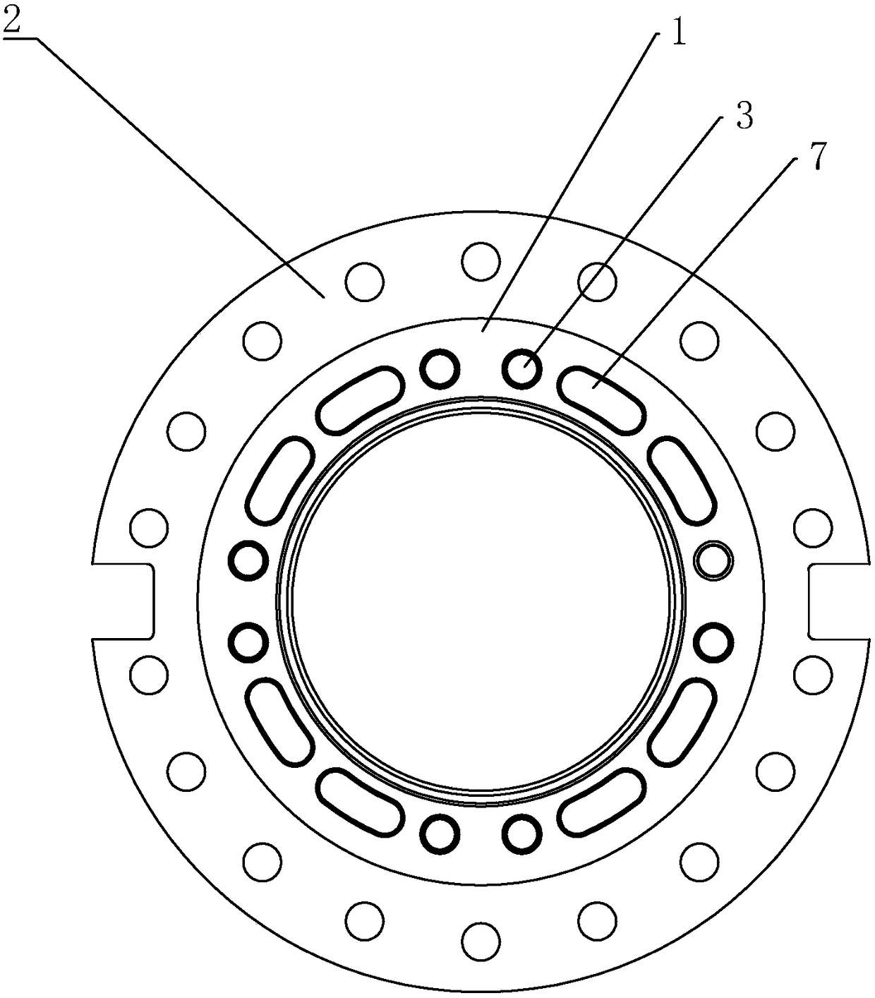
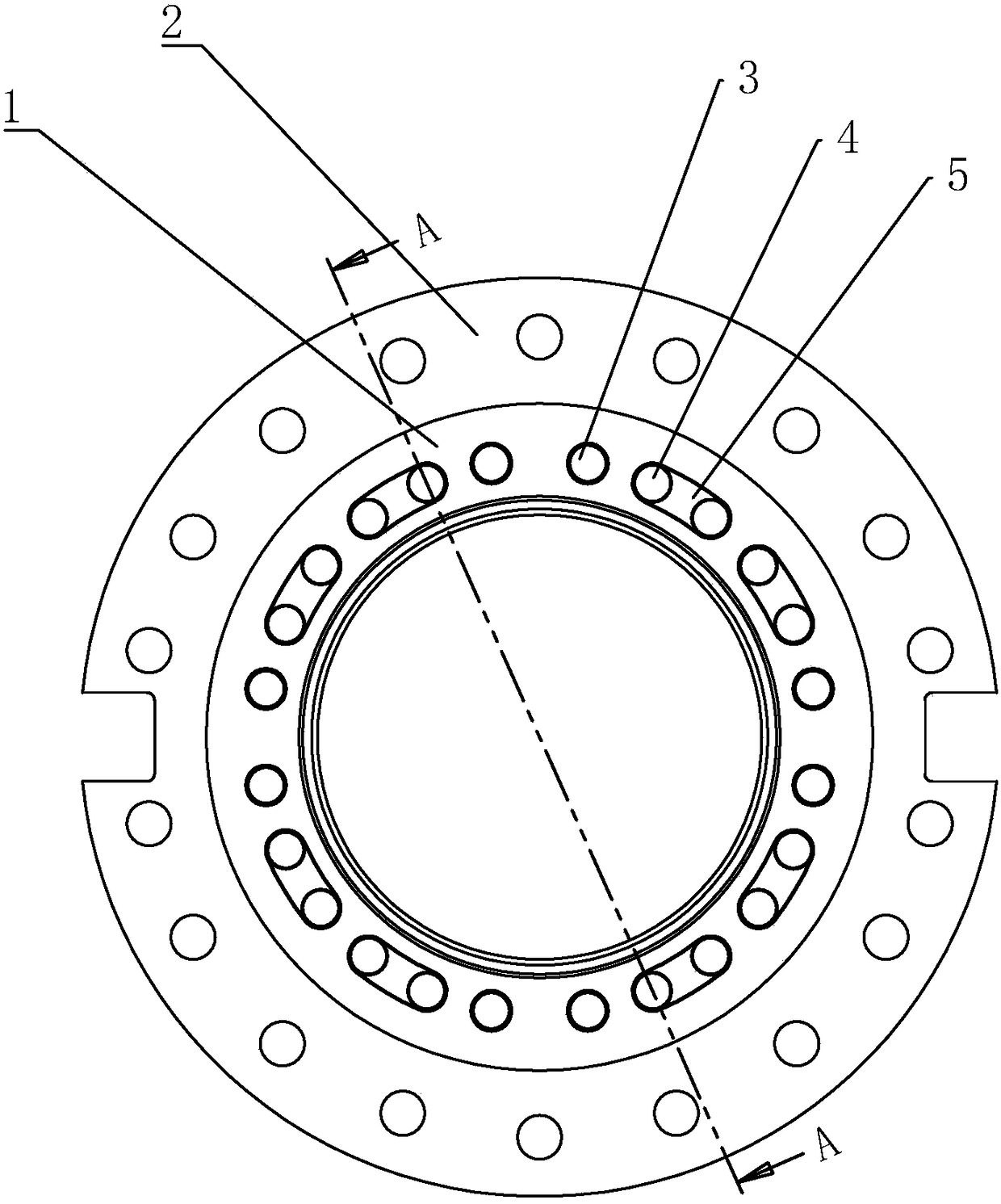
[0037] Embodiment 1: a kind of screw barrel cooling device, such as image 3 , 5As shown, it includes a screw barrel 1 and connecting flanges 2 at both ends of the screw barrel 1. The wall of the screw barrel 1 is provided with a number of first holes that run through both ends of the screw barrel 1 and are parallel to the axis of the screw barrel 1. The cooling channels 3 and the second cooling channels 4, the first cooling channels 3 and the second cooling channels 4 are evenly distributed on the screw barrel 1 in the circumferential direction, the first cooling channels 3 and the second The cooling channels 4 are arranged at intervals, and one end of the screw barrel 1 is provided with a first circulation groove 5 for the media in the adjacent first cooling channel 3 and the second cooling channel 4 to circulate, and the other end is provided with a communication groove 5. The second cooling channel 4 and the second circulation groove 6 of the other adjacent first cooling ...

Embodiment 2

[0044] Embodiment 2: The difference from Embodiment 1 is that first heat exchange blades 14 are helically arranged on the inner wall of the first cooling channel 3 along the axial direction of the first cooling channel 3 . Through the first heat exchange vanes 14 arranged on the inner wall of the first cooling channel 3, the medium flows in a spiral manner during the circulation process, which increases the circulation path of the medium and enables the medium to more fully communicate with the first cooling channel. The inner wall of a cooling channel 3 is in contact with the first heat exchanging blade 14, so that the medium can take away more heat in the process of circulation, thereby achieving the purpose of rapid cooling. Second heat exchange blades 15 are helically arranged on the inner wall of the second cooling channel 4 along the axial direction of the second cooling channel 4 . By adopting the above-mentioned technical solution, the second heat exchange blade 15 pro...


PUM


Abstract

The invention discloses a screw barrel cooling device and an extruder with the device, and belongs to the field. The screw barrel cooling device and the extruder with the device aim at evenly lowering the temperature in a charging barrel. According to the technical scheme, the screw barrel cooling device comprises a screw barrel and connecting flange plates at the two ends of the screw barrel. A plurality of first cooling channels and second cooling channels which penetrate the two ends of the screw barrel and are parallel to the axis of the screw barrel are arranged in the wall of the screw barrel. Water channel cover plates for preventing circulating media from being leaked are arranged on first circulating grooves and second circulating grooves. Cooling and circulating channels are formed by the first cooling channels and the second cooling channels through the first circulating grooves and the second circulating grooves, the four sets of cooling and circulating channels are arranged on the screw barrel in a circumferential array manner, and input holes and output holes communicating with the cooling and circulating channels end to end are formed in the screw barrel.

Description

technical field [0001] The invention relates to an extruder, in particular to a screw barrel cooling device. Background technique [0002] The heating system of the extruder generally uses the traditional resistance heating method to heat the raw materials in the barrel, which not only consumes a lot of power, but also produces serious heat pollution, low heat conversion efficiency, and 60% of the heat is lost Therefore, it is necessary to use a flow fan for cooling in the production workshop, which increases the cost of production and operation of the enterprise. At the same time, it is difficult for the traditional heating device to heat evenly, which greatly reduces the working reliability of the extruder. [0003] The Chinese patent with the notification number CN204936160U discloses a heating and cooling system for a single-screw barrel base of a reciprocating machine. The system includes two half-tubes, which are combined to form a barrel. The axial direction is provi...

Claims


Application Information

Patent Timeline
Patent Type & Authority Patents(China)
IPC IPC(8): B29C47/80
CPCB29C48/834
Inventor 张海军
Owner 镇江越升智能装备制造有限公司
Why Eureka
Try Eureka