Card connector

A card connector, electronic card technology, applied in the direction of connection, connecting device parts, electrical components, etc., can solve the problems of electronic card locking, slight floating, and the slider cannot be carried out, to prevent withdrawal, guarantee The effect of a smooth exit

Active Publication Date: 2012-09-19
KUNSHAN JIAHUA ELECTRONICS
View PDF5 Cites 6 Cited by
  • Summary
  • Abstract
  • Description
  • Claims
  • Application Information

AI Technical Summary

Problems solved by technology

However, when the above-mentioned anti-return locking piece interferes with the insulating body or the shielding housing, the slider cannot perform any slight floating, and then the electronic card is easily locked in the receiving space and cannot be withdrawn.

Method used


Image

  • Card connector
  • Card connector
  • Card connector

Examples


Embodiment Construction

[0022] In order to make the object, technical solution and advantages of the present invention clearer, the present invention will be described in detail below in conjunction with the accompanying drawings and specific embodiments.

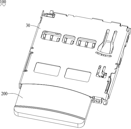
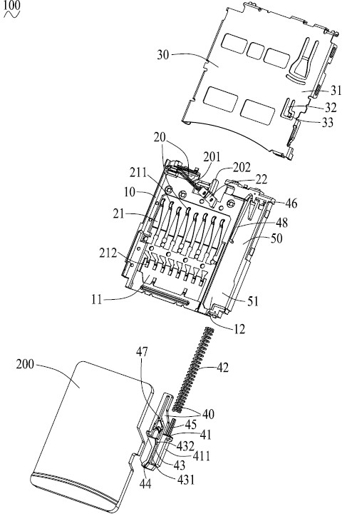
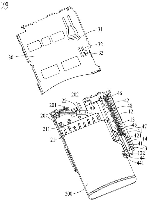
[0023] Such as figure 1 and figure 2 As shown, the card connector 100 of the present invention is used for inserting and docking an electronic card 200 (in this embodiment, a Micro SD card). The card connector 100 includes an insulating body 10 , a plurality of conductive terminals 20 fixed in the insulating body 10 , a card ejection mechanism 40 installed on the insulating body 10 and a shielding case 30 covering the insulating body 10 .

[0024] The insulating body 10 has a bottom wall, a first receiving slot 11 on the upper side of the bottom wall for receiving the docking electronic card 200 and a second receiving slot 12 for receiving the card ejection mechanism 40 . The first receiving groove 11 is adjacent to the second receiving groove...


PUM


Abstract

The invention provides a card connector. The card connector comprises an insulating body, a plurality of conductive terminals fixed in the insulating body, a card withdrawing mechanism mounted on the insulating body and a shielding casing for shielding the insulating body, wherein the card withdrawing mechanism consists of a sliding block movably positioned on the insulating body, and an open slot in along the insertion direction of a butt joint electric card is formed on the sliding block; the shielding casing is provided with an upper wall for shielding the insulating body, and a cantilever extending in the insertion direction of the butt joint electric card and a bending piece extending downwards in the thickness direction of the upper wall from the rear end of the cantilever are arranged on the upper wall; and the bending piece extends downwards and enters into the open slot, and the bending piece is capable of preventing the insulating body from shaking side to side when the card connector is in an operation state, so as to prevent the butt joint electric card from withdrawing.

Description

technical field [0001] The invention relates to a card connector, in particular to a card connector with an elastic bending piece on a shielding shell. Background technique [0002] A conventional card connector for receiving an electronic card generally includes an insulating body, a plurality of conductive terminals held on the insulating body, a card ejecting mechanism installed on the insulating body, and a shielding case covering the insulating body. The insulating body and the shielding case form a receiving space for receiving the electronic card. The card ejecting mechanism includes a slide block installed on the insulating body, a spring arranged between the slide block and the insulating body, and an anti-retraction locking sheet buckled with the electronic card. The electronic card can be inserted into or withdrawn from the above-mentioned card connector through interaction with the card ejection mechanism. [0003] When the existing card connector is in the wor...

Claims


Application Information

Patent Timeline
Patent Type & Authority Applications(China)
IPC IPC(8): H01R13/516H01R13/639H01R13/633H01R12/71
Inventor 周芝福邵明波
Owner KUNSHAN JIAHUA ELECTRONICS
Why Eureka
Try Eureka