

Display device
A technology for display devices and display units, applied in optics, instruments, electrical components, etc., can solve problems such as crosstalk and reduce visibility, and achieve the effect of suppressing moiré
- Summary
- Abstract
- Description
- Claims
- Application Information
AI Technical Summary
Problems solved by technology
Method used
Image

Examples
no. 1 example
[0025] [Example of Configuration of Stereoscopic Image Display Device]
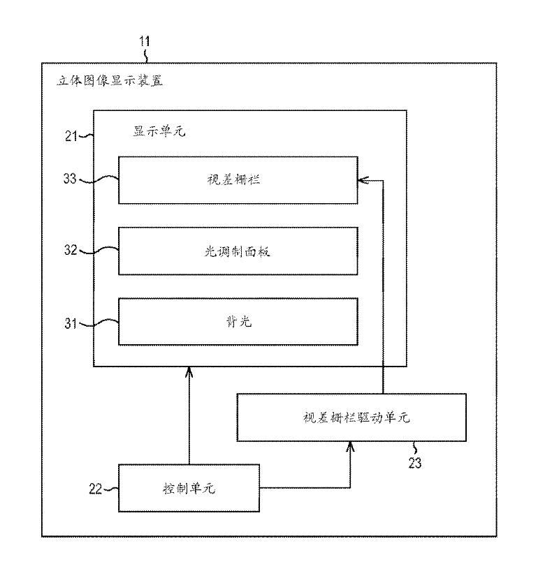
[0026] figure 1 is a view showing an example of the configuration of a stereoscopic image display device of an embodiment of the present disclosure.
[0027] The stereoscopic image display device 11 displays a stereoscopic image and a planar image while performing display switching between a three-dimensional stereoscopic image based on the parallax barrier method and a two-dimensional planar image as needed. The stereoscopic image display device 11 is configured to include a display unit 21 , a control unit 22 and a parallax barrier driving unit 23 .
[0028] The display unit 21 includes a backlight 31, a light modulation panel 32, and a parallax barrier 33, and displays images including an image for the right eye observed (perceived) by the right eye of the observer and an image for the left eye observed by the left eye of the observer. 2D planar image or 3D stereoscopic image.
[0029] That is to sa...
no. 2 example
[0102] [About the configuration of the filter area]
[0103] In addition, although the above describes the case where only one edge side of the filter area of each sub-pixel is provided along the y-direction, the light-shield areas may also be provided on both edge sides of the filter area in the y-direction.
[0104] In this case, as Image 6 as shown in e.g. figure 2 In each sub-pixel of the light modulation panel 32 shown, the light-shielding area is set to sandwich the light-filtering area. in addition, Image 6 neutralize figure 2 Parts corresponding to the respective parts in are denoted by the same reference numerals, and explanations thereof will be appropriately omitted.
[0105] In addition, in Image 6 A portion of the light modulating panel 32 and the switching liquid crystal layer 84 are shown in . exist Image 6 In , the horizontal direction, vertical direction and depth direction represent the x, y and z directions, respectively. also, Image 6 In t...
no. 3 example
[0118] [About the configuration of the filter area]
[0119] Although the above describes the case of displaying a stereoscopic image including an image for the left eye and an image for the right eye, the stereoscopic image display device 11 may also display a multi-viewpoint stereoscopic image including a plurality of images of three or more viewpoints.
[0120] In this case, for example, as Figure 7 As shown, sub-pixels having color filters of R, G, and B colors are arranged on the filter surface of the light modulation panel 32 . in addition, Figure 7 neutralize figure 2 Parts corresponding to the respective parts in are denoted by the same reference numerals, and explanations thereof will be appropriately omitted. in addition, Figure 7 In , the horizontal direction, vertical direction and depth direction are assumed to be x, y and z directions, respectively. In addition, in Figure 7 In the example shown, the switching liquid crystal layer 84 , ie the parallax b...
PUM
 Abstract
Description
Claims
Application Information