
Flow control switching valve for automobile emergency steering system

An emergency steering and flow control technology, applied in fluid pressure actuating devices, servo motor components, mechanical equipment, etc., can solve problems such as vehicle steering failure, non-compliance, and easy occurrence of safety accidents, so as to improve system life and improve safety. performance effect

Active Publication Date: 2012-09-26
秦川机床工具集团股份公司
View PDF4 Cites 2 Cited by
  • Summary
  • Abstract
  • Description
  • Claims
  • Application Information

AI Technical Summary

Problems solved by technology

[0002] With the development of the automobile industry and the increase of the load quality of the automobile, the existing hydraulic steering system can meet the GB17675 standard and the European standard EN 71 / 311 / EEC under normal working conditions, but when the durability of the system decreases or fails, the automobile steering system failure, does not meet the requirements of the above standards, and is very prone to safety accidents. In this case, the emergency steering system is applied. In this system, an emergency valve is required to switch between the emergency steering pump and the main steering pump. To realize the automatic switching of the oil supply flow of two steering oil pumps to the steering gear, but the current valve body cannot meet the demand

Method used


Image

  • Flow control switching valve for automobile emergency steering system
  • Flow control switching valve for automobile emergency steering system
  • Flow control switching valve for automobile emergency steering system

Examples


Embodiment Construction

[0024] The present invention will be described in further detail below in conjunction with the accompanying drawings.

[0025] Firstly, the structure of each component of the present invention will be described separately.

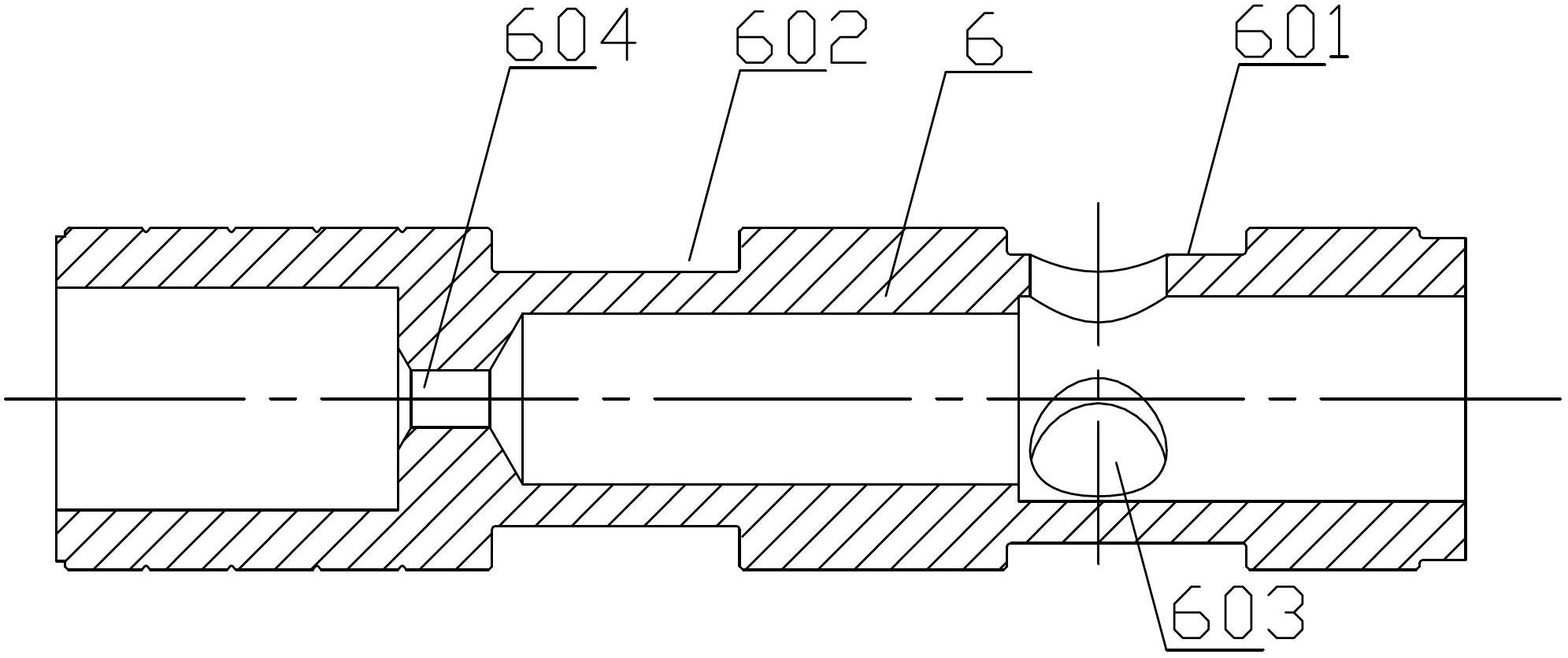
[0026] Such as figure 1 As shown, the outer surface of the main valve core 6 of the present invention is perpendicular to its length direction and is successively provided with spaced first grooves 601 and second grooves 602, the first groove 601 is closer to the oil inlet of the main steering pump, and the second There are three small holes 603 leading to the inside of the main valve core 6 on a groove 601, and a small-diameter oil hole 604 is arranged inside the main valve core 6, and the inside of the main valve core 6 appears to be connected by the small-diameter oil hole 604. There are two chambers. In this embodiment, the one directly connected to the oil inlet of the main steering pump is the right chamber, and the other is the left chamber. The di...


PUM


Abstract

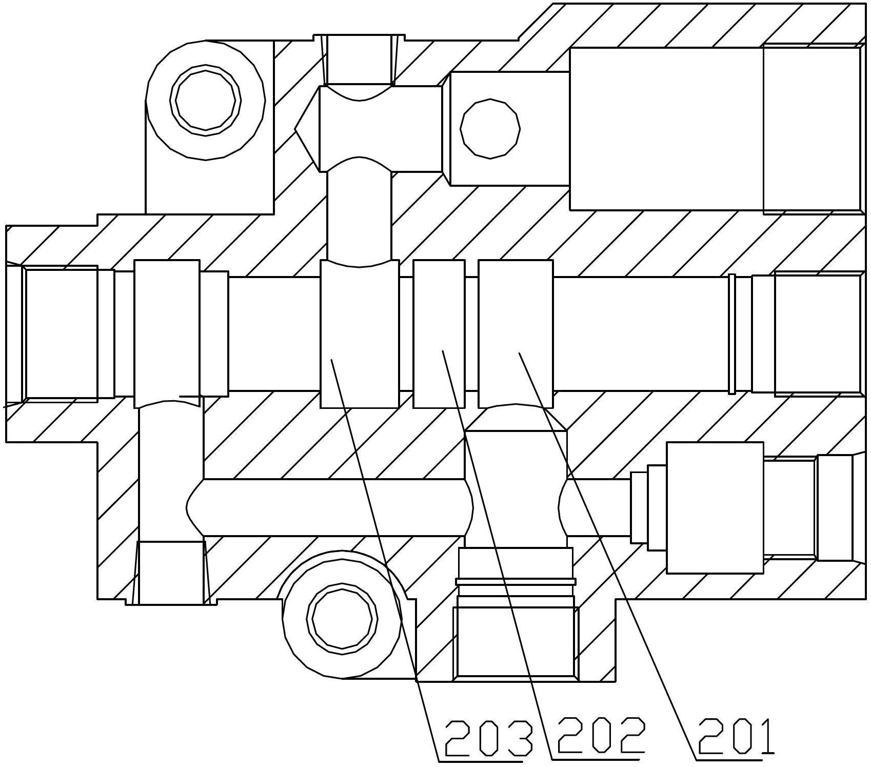
A flow control switching valve for an automobile emergency steering system adopts the structure that a transversal main valve core is arranged in the middle of the valve body; a first groove and a second groove are sequentially formed in the outer side surface of the main valve core in a direction perpendicular to the length direction; a small hole leading to the interior of the main valve core is formed in the first groove; one end of the main valve core, which is near the second groove, is connected with a small check valve through a first spring; the other end of the main valve core serves as the oil inlet of a main steering pump; a large check valve is arranged on the lower side of the main valve cover; the bottom end of the large check valve is an oil outlet; a channel is arranged between the small check valve and the large check valve; a first annular groove, a second annular groove and a third annular groove, which are coaxial with the main valve core, are formed in the valve body; the first annular groove corresponds to the top end of the large check valve; the second annular groove is connected with the oil inlet of an emergency pump; and the third annular groove is connected with the oil return port of the emergency pump. The flow control switching valve can be used for automatically switching the oil supply flow rates of two steering oil pumps which supply oil to a steering machine, and when the flow rate of one oil pump in the system is smaller than the set flow rate of the system, the flow control switching valve gives out an alarm automatically for prompt.

Description

technical field [0001] The invention belongs to a hydraulic steering system, relates to an automobile emergency steering system, in particular to a flow control switching valve used in an automobile emergency steering system. Background technique [0002] With the development of the automobile industry and the increase of the load quality of the automobile, the existing hydraulic steering system can meet the GB17675 standard and the European standard EN 71 / 311 / EEC under normal working conditions, but when the durability of the system decreases or fails, the automobile steering system failure, does not meet the requirements of the above standards, and is very prone to safety accidents. In this case, the emergency steering system is applied. In this system, an emergency valve is required to switch between the emergency steering pump and the main steering pump. To realize the automatic switching of the oil supply flow of two steering oil pumps to the steering gear, but none of ...

Claims


Application Information

Patent Timeline
Patent Type & Authority Applications(China)
IPC IPC(8): F15B13/02
Inventor 雷洪闯王小侠李红亮张晓航杨斌闫维军
Owner 秦川机床工具集团股份公司
Learn More