Buoy switch

A floating body and switch technology, applied in the direction of robot floating motion actuation, etc., can solve the problems of equipment damage, dry burning, liquid level lower than electric heating/electrolytic components, etc., and achieve the effect of avoiding dry burning

Inactive Publication Date: 2012-09-26
张秀英
View PDF5 Cites 6 Cited by
  • Summary
  • Abstract
  • Description
  • Claims
  • Application Information

AI Technical Summary

Problems solved by technology

[0002] During the use of electric water heaters, electrolytic devices and other equipment, when air enters the container and causes the liquid level to dro

Method used


Image

  • Buoy switch
  • Buoy switch
  • Buoy switch

Examples


Embodiment Construction

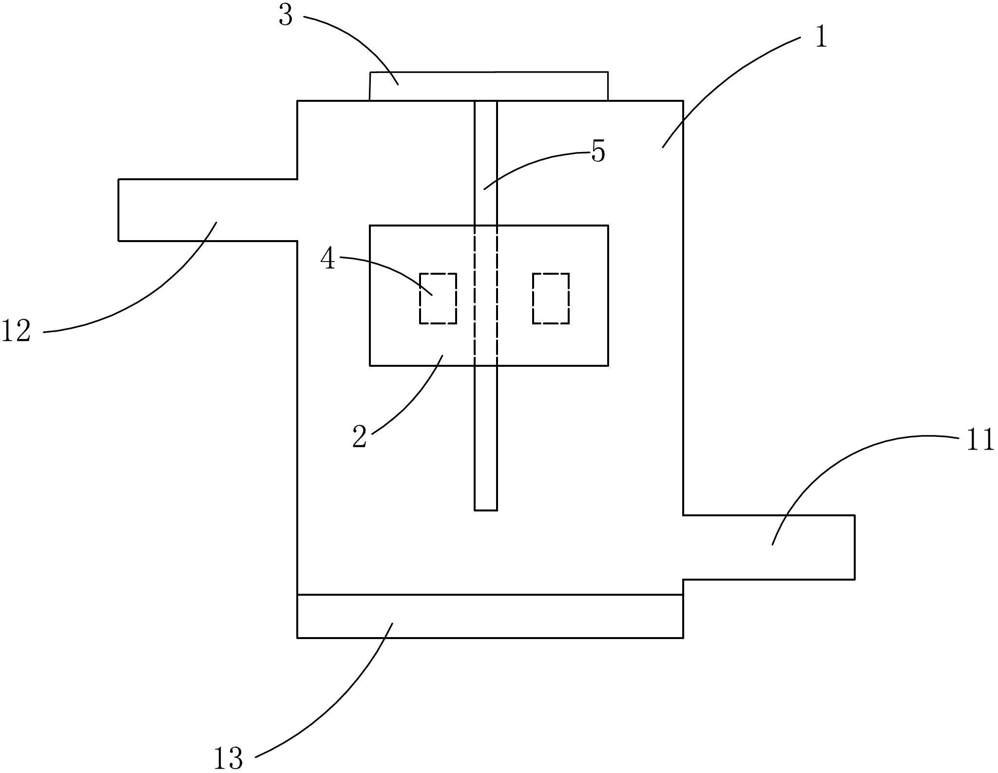
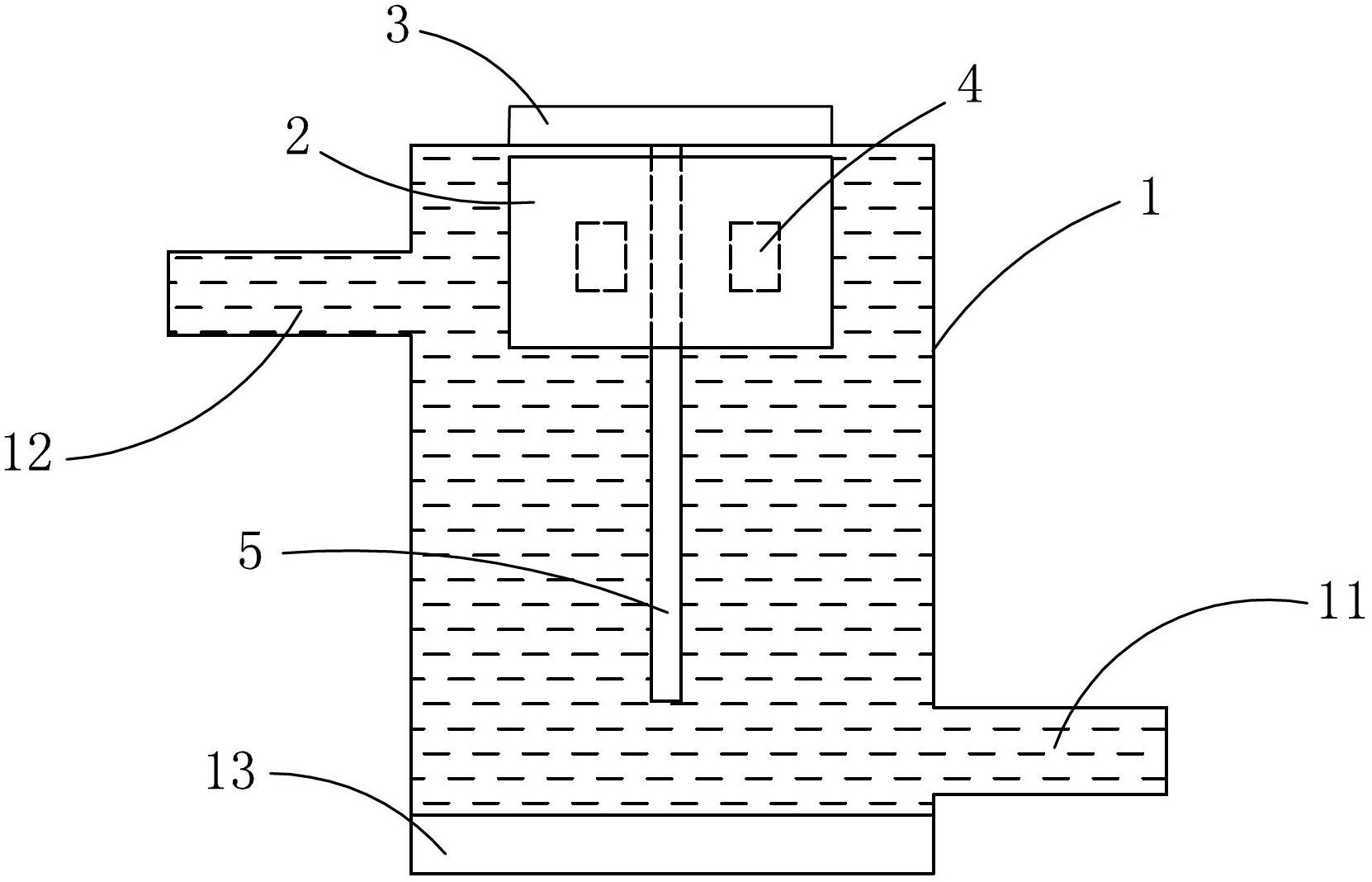
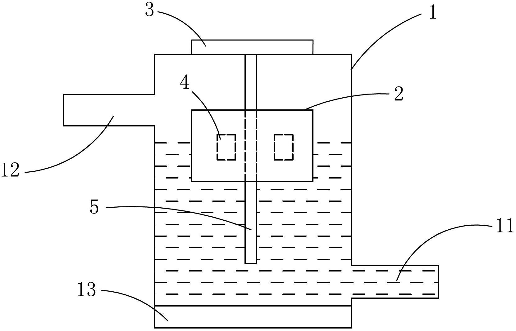
[0014] figure 1 An embodiment of a floating body switch provided by the present invention, its main body is an airtight container 1, the airtight container 1 is provided with a water inlet 11 and a water outlet 12, the water inlet 11 is connected to a water source, and the water outlet 12 is connected to an electric water heater, an electrolysis device and other equipment , the airtight container 1 is vertically provided with a guide post 5, and a floating body 2 is movable on the guide post 5. The floating body 2 is made of a material with a lower density so that it can float above the liquid in the airtight container 1, and the floating body 2 follows the liquid. The surface lift moves up and down along the guide post 5. A reed switch 3 is arranged on the top of the airtight container 1, and a magnet 4 is arranged in the floating body 2. The reed switch 3 and the magnet 4 form a reed relay, which can be used to control power switches of electric water heaters, electrolysis d...


PUM


Abstract

The invention discloses a buoy switch which comprises a closed container with a water inlet and a water outlet. A buoy is arranged inside the closed container, a reed switch is disposed on the top of the closed container, a magnet is arranged in the buoy, and the reed switch and the magnet form a reed relay. The buoy switch is applicable to equipment such as an electric water heater and an electrolysis device, can control on or off of a power source of the equipment according to ascending and descending of the liquid level, and accordingly prevents dry heating.

Description

technical field [0001] The invention relates to a switch, in particular to a switch using a floating body to form a dry reed relay. Background technique [0002] During the use of electric water heaters, electrolytic devices and other equipment, when air enters the container and causes the liquid level to drop, the liquid level is prone to be lower than the electric heating / electrolytic element, resulting in dry burning and causing great damage to the equipment. Contents of the invention [0003] In order to solve the above-mentioned technical problems, the object of the present invention is to provide a floating body switch with a simple structure, which can avoid dry burning of electric water heaters, electrolyzed water devices and other equipment. [0004] The technical scheme adopted in the present invention is mainly: [0005] A float switch, comprising a closed container provided with a water inlet and a water outlet, a floating body is arranged inside the closed co...

Claims


Application Information

Patent Timeline
IPC IPC(8): H01H36/02
Inventor 陈振圳
Owner 张秀英
Why Eureka
Try Eureka