Shielding box

A shielding box, an integrated technology, applied in the fields of magnetic/electric field shielding, electrical components, etc., can solve the problems of increasing the manufacturing time and cost of the shielding box, and achieve the effect of omitting the welding process and reducing the manufacturing time and cost.

Inactive Publication Date: 2012-09-26
KUNSHAN WEIJIN HARDWARE PROD
View PDF3 Cites 2 Cited by
  • Summary
  • Abstract
  • Description
  • Claims
  • Application Information

AI Technical Summary

Problems solved by technology

In the existing shielding box, after cutting and bending the metal sheet, welding is used to complete the contact between t

Method used


Image

  • Shielding box
  • Shielding box
  • Shielding box

Examples


Embodiment Construction

[0013] The present invention will be further described below in conjunction with the accompanying drawings.

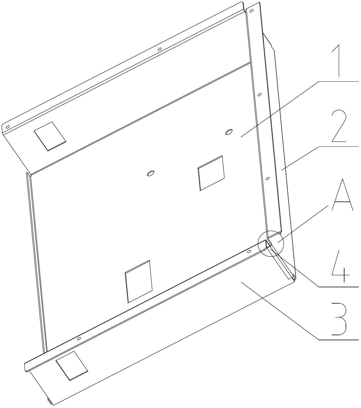
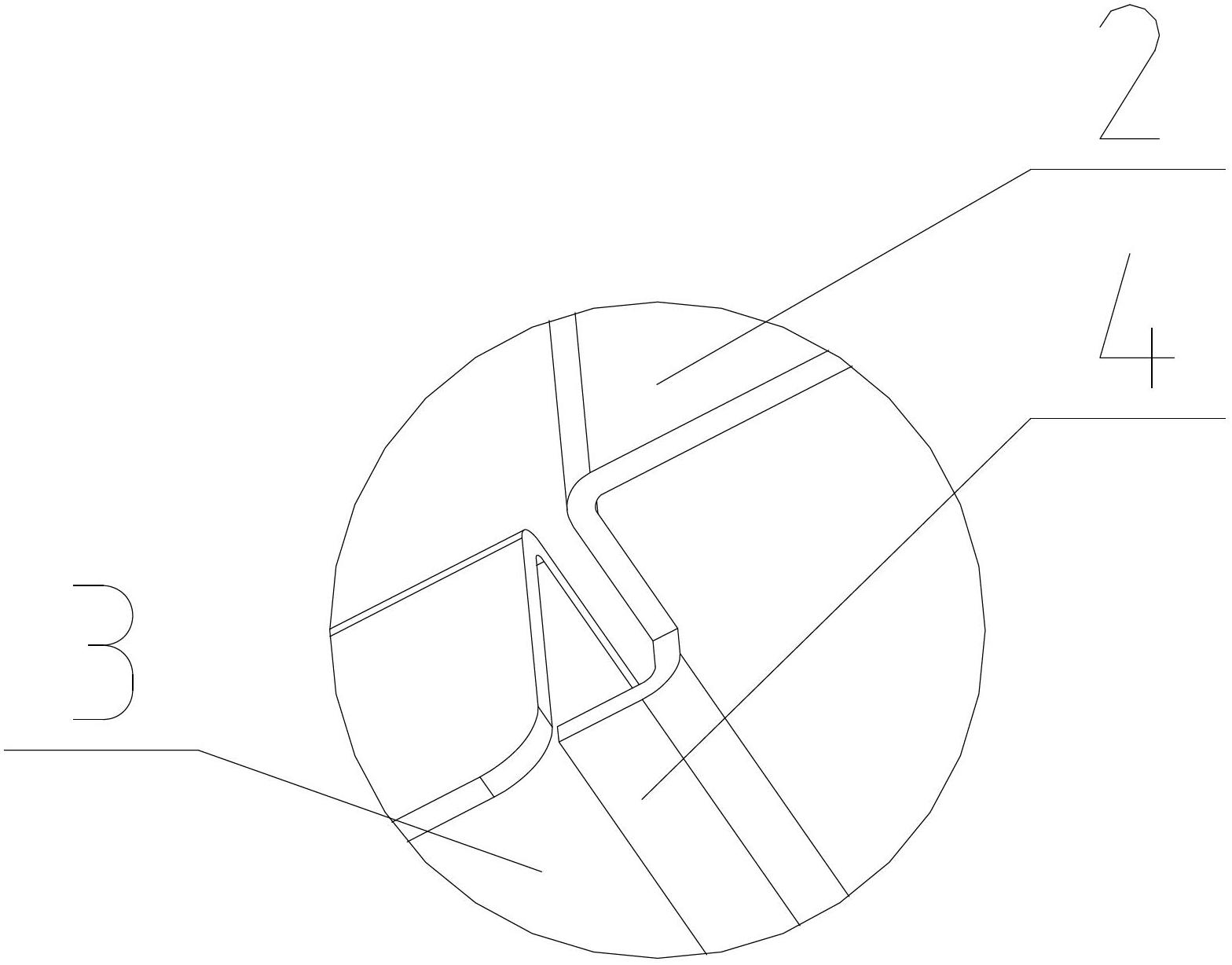
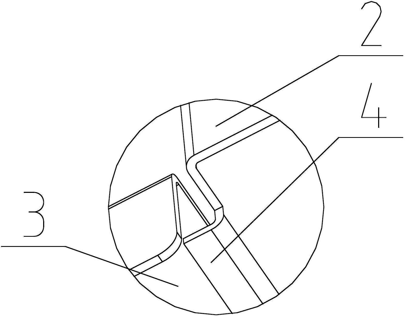
[0014] Such as figure 1 , figure 2 Shown is a shielding box with an integrated structure, including a bottom plate 1 and a side plate, and the two adjacent side plates are respectively marked as A side plate 2 and B side plate 3, and the A side plate 2 is in contact with the B side plate 3 There is a bent part 4 extending on one side of the side, and the bent part 4 is overlapped on the outer surface of the B side plate 3; the overlapping width of the bent part 4 and the B side plate 3 is greater than 5mm, and the bent The angle between the part 4 and the A side plate 2 is less than or equal to the angle between the B side plate 3 and the A side plate 2 .

[0015] The above is only a preferred embodiment of the present invention, it should be pointed out that for those of ordinary skill in the art, without departing from the principle of the present invention, some ...


PUM

PropertyMeasurementUnit
Lap widthaaaaaaaaaa

Abstract

The invention discloses a shielding box. The shielding box comprises a bottom board and side boards, wherein two adjacent side boards are respectively marked as a side board A and a side board B, one side of the side board A, which is connected with the side board B, is provided with a bending part in an extension way, and the bending part is lapped on the outer side surface of the side board B. The shielding box provided by the invention has the advantages that the connection between the two adjacent side boards is realized through a lapping structure of the bending part, a welding technical process is omitted, and the manufacturing time and the manufacturing cost of the shielding box are reduced.

Description

technical field [0001] The invention relates to a shielding box structure, in particular to a shielding box used in household appliances and manufactured only by cutting and bending metal plate processes. Background technique [0002] In order to prevent the interference of high-frequency electromagnetic fields on the circuit, anti-electromagnetic interference is an important part of the structural design of high-frequency circuits. The existing method is to install the circuit that generates high-frequency signals or the circuit that works in the high-frequency electromagnetic field environment in a metal shielding box. middle. In the existing shielding box, after cutting and bending the metal plate, welding is used to complete the contact between the sides. The increase of the welding process will undoubtedly increase the manufacturing time and cost of the shielding box. Contents of the invention [0003] Purpose of the invention: In order to overcome the deficiencies i...

Claims


Application Information

Patent Timeline
IPC IPC(8): H05K9/00
Inventor 朱安邦
Owner KUNSHAN WEIJIN HARDWARE PROD
Why Eureka
Try Eureka