Construction of coupling exhaust pipes of vehicle

A connection structure and exhaust pipe technology, applied in the direction of flange connection, exhaust device, pipe/pipe joint/pipe fitting, etc., can solve the problems of increased weight and cost, large number of parts, troublesome welding process, etc., to achieve Avoidance of weight, ease of manufacture, effect of reduced quantity

Active Publication Date: 2008-12-31
NAKAGAWA SANGYO
View PDF10 Cites 0 Cited by
  • Summary
  • Abstract
  • Description
  • Claims
  • Application Information

AI Technical Summary

Problems solved by technology

[0005] However, the structure of the above-mentioned prior art needs to fix the connection flanges 61, 62 or the snap rings 71, 72 on the pipe end outer peripheries of the exhaust pipes 1, 2 by welding, so not only the stress concentrates on the weld joint but also the There is a problem that it is easy to break due to the vibration of the vehicle, and there is also a problem that the welding process is troublesome.
Furthermore, in the first prior art example, if the surface pressure is raised in order to prevent the gasket 63 from leaking gas, it is necessary to make the connection flanges 61, 62 thicker by 10 to 12 mm, which increases the weight and cost. problem, and in the second prior art example, there is a problem of a large number of parts

Method used


Image

  • Construction of coupling exhaust pipes of vehicle
  • Construction of coupling exhaust pipes of vehicle
  • Construction of coupling exhaust pipes of vehicle

Examples


Embodiment Construction

[0026] (First Embodiment)

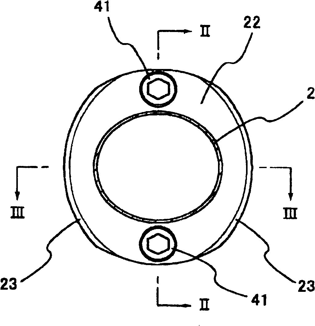
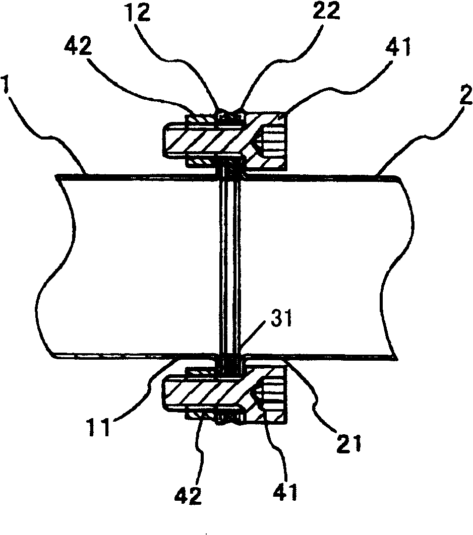
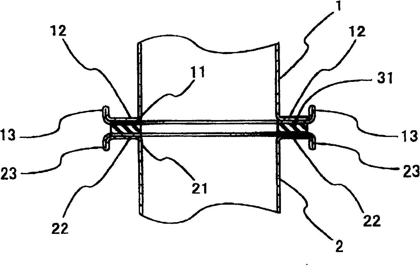
[0027] Figure 1 ~ Figure 3 An example of the connection structure of the present invention is shown. figure 1 Is a cross-sectional view of the connected vehicle exhaust pipe, figure 2 , image 3 Respectively along figure 1 The vertical cross-sectional view of the II-II line and the III-III line. in figure 2 , image 3 Among them, the upstream side exhaust pipe 1 and the downstream side exhaust pipe 2 are located such that the opening edges 11 and 21 face each other. The wall thickness of each exhaust pipe 1, 2 is, for example, 1.2 to 1.5 mm, and its opening edges 11, 21 are expanded and formed to bend outward in the radial direction, and then fold inward in the radial direction to form a convex of a predetermined width around the opening. Rim 12,22. The flanges 12 and 22 are provided with a gasket 31 between them, butt against each other, and are symmetrical in the radial direction ( figure 1 ) Combine with bolt 41 and nut 42. The two exhaust pip...


PUM


Abstract

The invention provides a connection structure of a vehicle exhaust pipe, in which the opening edges (11, 21) of the upstream exhaust pipe (1) and the downstream exhaust pipe (2) face each other along the radial direction by expanding and forming After being bent outward, it is folded inward along the radial direction to form a flange portion (12, 22). The two flange parts (12, 22) are butted through the gasket (31), and are mechanically resisted and combined with each other by bolts (41) and nuts (42).

Description

Technical field [0001] The present invention relates to a connection structure of vehicle exhaust pipes, and in particular to a connection structure that can connect exhaust pipes to each other without welding and with a small number of parts. Background technique [0002] Figures 11 and 12 show an example of a conventional exhaust pipe connection structure. In FIG. 12, the pipe ends of the upstream exhaust pipe 1 and the downstream exhaust pipe 2 are fixed by welding with substantially diamond-shaped (FIG. 11) connecting flanges 61, 62, and bolts 64 and nuts 65 are used. The connecting flanges 61 and 62 are connected via the gasket 63, and the two exhaust pipes 1 and 2 are thus connected together (first prior art example). [0003] Fig. 13 and Fig. 14 show other examples of the conventional exhaust pipe connection structure. In FIG. 14, the entire circumference of one side of the locking rings 71 and 72 formed in a U-shaped cross-section is welded and fixed to the outer circumfe...

Claims


Application Information

Patent Timeline
Patent Type & Authority Patents(China)
IPC IPC(8): F01N7/18F01N7/08F16L23/04F01N13/18F01N13/08
Inventor 中川幸弘
Owner NAKAGAWA SANGYO
Why Eureka
Try Eureka