Skin observation device

A technology for observing devices and skin, applied in measuring devices, sensors, diagnosis, etc., can solve problems such as inability to compare images

Inactive Publication Date: 2012-09-26
MORITEX CORP
View PDF7 Cites 1 Cited by
  • Summary
  • Abstract
  • Description
  • Claims
  • Application Information

AI Technical Summary

Problems solved by technology

[0012] Therefore, during repeated button operations, the skin observation device touching the skin may move, and for example, even if it is necessary to compare and explain th

Method used


Image

  • Skin observation device
  • Skin observation device
  • Skin observation device

Examples


Embodiment 1

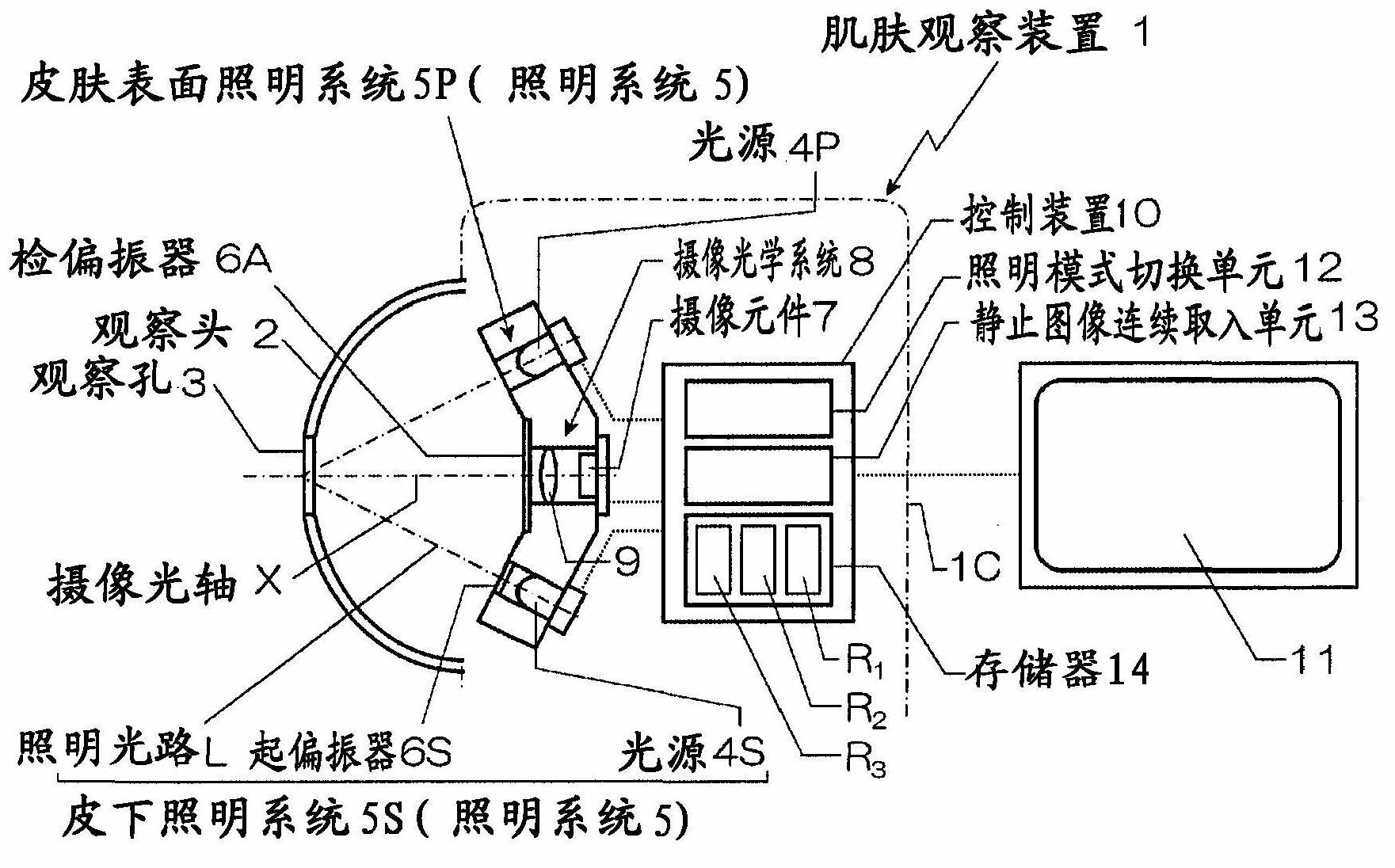
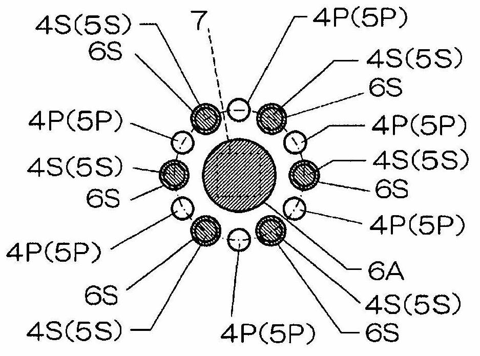
[0029] exist figure 1 In the shown skin observation device 1 , an observation hole 3 is formed in the observation head 2 that abuts against the skin to be observed, and a light source 4P that irradiates illumination light to the observation hole 3 is disposed inside the observation head 2 . , an illumination system 5 of 4S, and an imaging optical system 8 including an imaging element 7 that captures a reflected light image from an object to be observed.

[0030] The illumination system 5 includes a skin surface illumination system 5P that directly irradiates light irradiated from the light source 4P in a non-polarized state, and a subcutaneous observation illumination system 5S that irradiates the light irradiated from the light source 4S in a linearly polarized state through a polarizer 6S. In this system, the polarizer 6S is arranged on the illumination light path L from the light source 4S to the observation hole 3 .

[0031] In the imaging optical system 8, on the imaging...

Embodiment 2

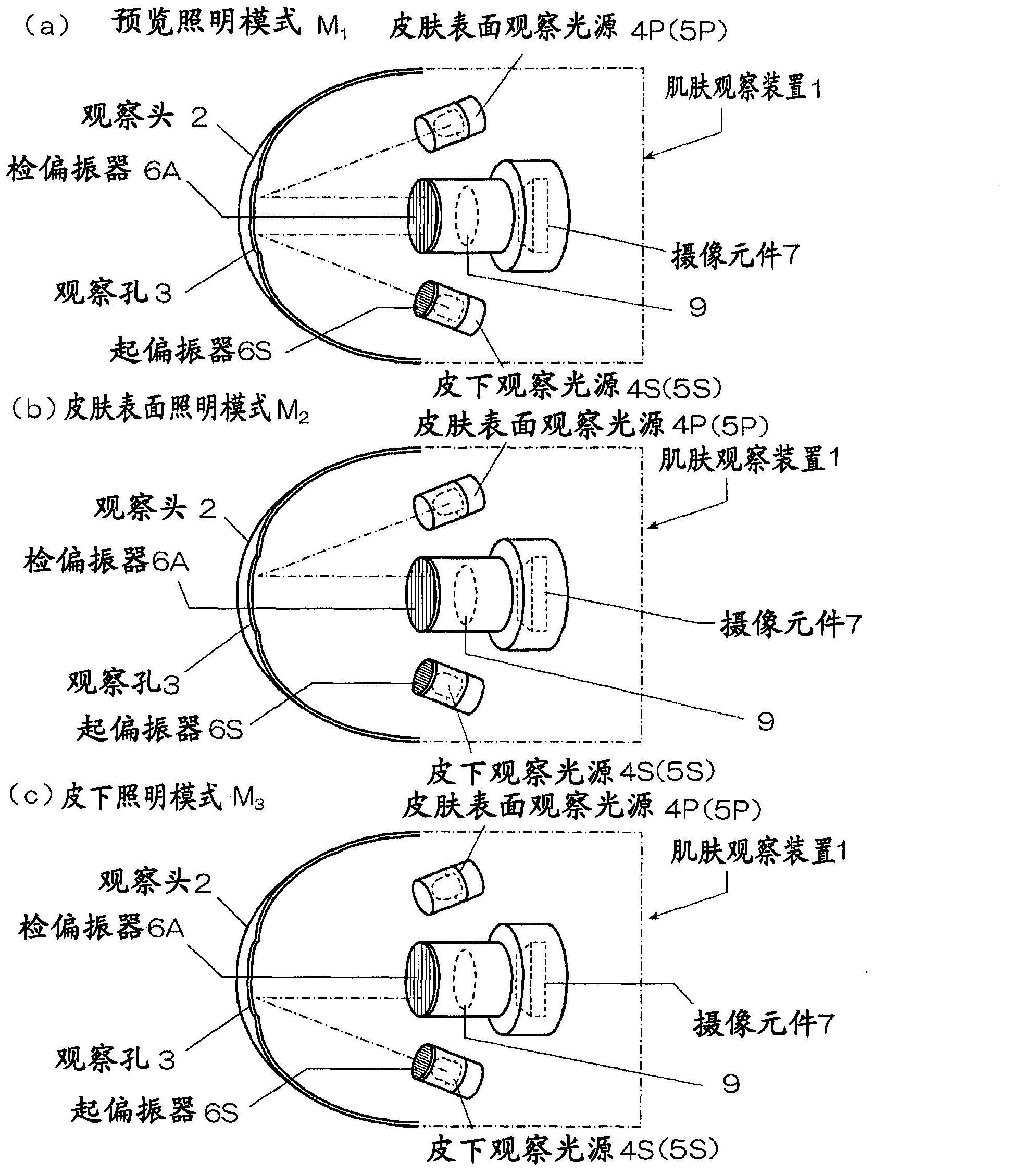
[0054] In the above description, it was explained that when the preview lighting mode M 1 , skin surface lighting mode M 2 and subcutaneous lighting mode M 3 When shooting a still image in one course in which these three lighting modes are lit in this order, it is also possible to register a lighting course in which the lighting order of any two lighting modes is set in addition to this course. , choose the lighting method at any time.

[0055] In this case, in the lighting mode switching unit 12, for example, the preview lighting mode M is registered. 1 , skin surface lighting mode M 2 and subcutaneous lighting mode M 3 These three lighting modes are illuminated in this order C 1 , enable preview lighting mode M 1 and skin surface lighting mode M 2 Lighting pattern C that lights up in this order 2 , and enable preview lighting mode M 1 and subcutaneous lighting mode M 3 Lighting pattern C that lights up in this order 3 .

[0056] In addition, in advance, which lig...

Embodiment 3

[0069] Examples 1 and 2 both use the preview lighting mode M 1 , skin surface lighting mode M 2 and subcutaneous lighting mode M 3 In the case of these three lighting modes, in this example, it is not necessary to turn on the skin surface lighting system 5P and the subcutaneous lighting system 5S at the same time, but to turn on the skin surface lighting system 5P so that the skin surface lighting mode M can also be used. 2 and preview lighting mode M 1 .

[0070] Image 6 is a flowchart showing its processing procedure.

[0071] In this example, when the main switch (not shown) is turned ON, the processing starts. First, if the skin surface lighting mode M is set in step STP21 2, only the light source 4P of the skin surface illumination system 5P is turned on, the imaging optical system 8 is turned ON in step STP22 , and the moving image output from the imaging element 7 is displayed on the display 11 .

[0072] Then, in step STP23 , the composition is determined while ...


PUM


Abstract

Disclosed is a skin observation device which is capable of continuously capturing respective images by individually turning on light sources of a skin surface illumination system and a subcutaneous illumination system by one action without the troublesome operation of buttons. For this, a control device (10) for controlling the turning-on timing of the respective illumination systems (5P, 5S) and the timing of the image-capturing by an image capturing element (7) is provided with: an illumination mode switch means (12) which switches between at least two illumination modes in a preset order, the two illumination modes being a skin surface illumination mode (M2) of illuminating by the skin surface illumination system (5P) and a subcutaneous illumination mode (M3) of illuminating by the subcutaneous illumination system (5S); and a static image continuously capturing means (13) which continuously captures the static images of the respective illumination modes (M2, M3) while switching between the illumination modes by the illumination mode switch means (12) when a predetermined trigger signal is oriented.

Description

technical field [0001] The present invention relates to a skin observation device that magnifies and takes an image of the skin by contacting an observation hole of the skin to be observed. Background technique [0002] The skin observation device is used as a sales promotion tool for selling skin care products optimal for a customer's skin in beauty salons (cosmetics stores) and the like. [0003] Conventional skin observation devices are generally equipped with a dome-shaped observation head with an observation hole formed at the front end. By touching the observation head to any part where you want to observe the skin, such as cheeks, temples, and under the eyes, the skin of the customer can be monitored. The appearance is zoomed in for observation. [0004] In this case, the surface reflected light reflected on the skin surface contains information on the surface state of the skin such as skin cracks and texture (skin lines), and the internal reflected light scattered i...

Claims


Application Information

Patent Timeline
IPC IPC(8): G02B21/06A61B5/00A61B5/107G01N21/17G01N21/21
CPCG02B21/0092A61B5/442A61B5/441G02B21/084
Inventor 大迫秀隆丰田诚
Owner MORITEX CORP
Why Eureka
Try Eureka