Skin observation system

a skin observation and skin technology, applied in the field of skin observation system, can solve the problem of reference providing measures for adequately shielding or filtering ligh

Inactive Publication Date: 2019-06-20
OMM IMPORTS INC
View PDF6 Cites 2 Cited by
  • Summary
  • Abstract
  • Description
  • Claims
  • Application Information

AI Technical Summary

Benefits of technology

[0004]It is accordingly an object of the invention to provide a skin observation system, which overcomes the hereinafore-mentioned disadvantages of the heretofore-known devices of this general type and which provides the user with the ability to observe and understand his or her skin condition with the user's own eyes, without the intermediary of cameras and virtual reality elements and which adequately protects the eyes of the user.
[0007]In accordance with another feature of the invention, the mirror has a concave surface directed toward the face of the user. The mirror is adjustable in position toward and away from the face of the user so that different users can be accommodated. The concavity is provided to focus the eyes of the user, to make the image in the mirror appear larger and to make the vision field narrower to prevent the user from seeing reflections of and flashes of light.
[0008]In accordance with a further feature of the invention, the lighting device includes a plurality of laser diodes disposed along two rows, one of the rows is disposed below and another of the rows is disposed above the mirror, so they will illuminate the entire relevant part of the face without shadows. The laser diodes provide a narrow spectral strip, they do not focus but they do use a light spreading filter. The laser diodes raise the signal-to-noise ratio and allow the user's own eyes to see the true condition of the skin through simple filters.
[0013]In accordance with yet an additional feature of the invention, the ultraviolet light filter has a concave surface directed toward the face of the user, one end attached to an inner surface of the helmet, and a free end extending below the line of sight of the user wearing the helmet. The filter protects the eyes from light in the ultraviolet region of the electromagnetic spectrum.
[0015]In accordance with a concomitant feature of the invention, a preferably black lining extends entirely over an inner surface of the helmet for absorbing light and preventing reflections of light.

Problems solved by technology

None of the prior art references provide measures for adequately shielding or filtering light so that it is not harmful to the eyes of the user.

Method used


Image

  • Skin observation system
  • Skin observation system

Examples


Embodiment Construction

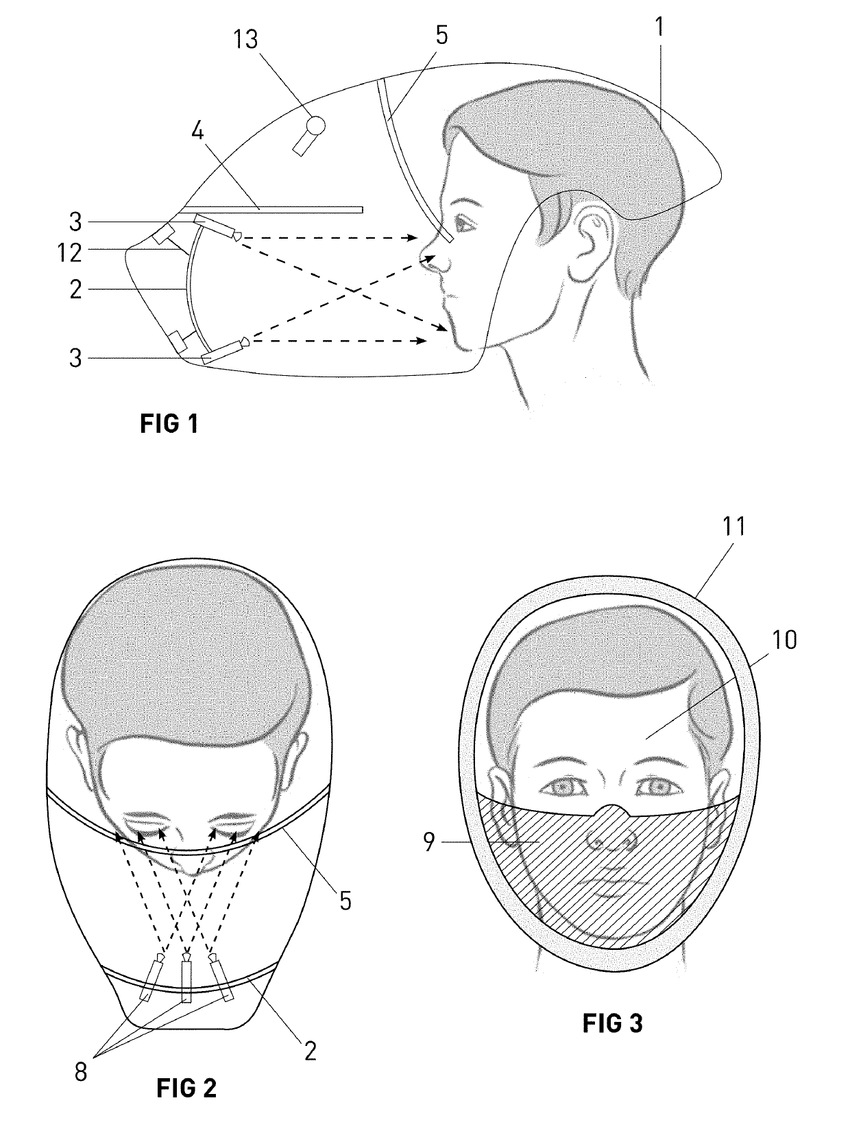
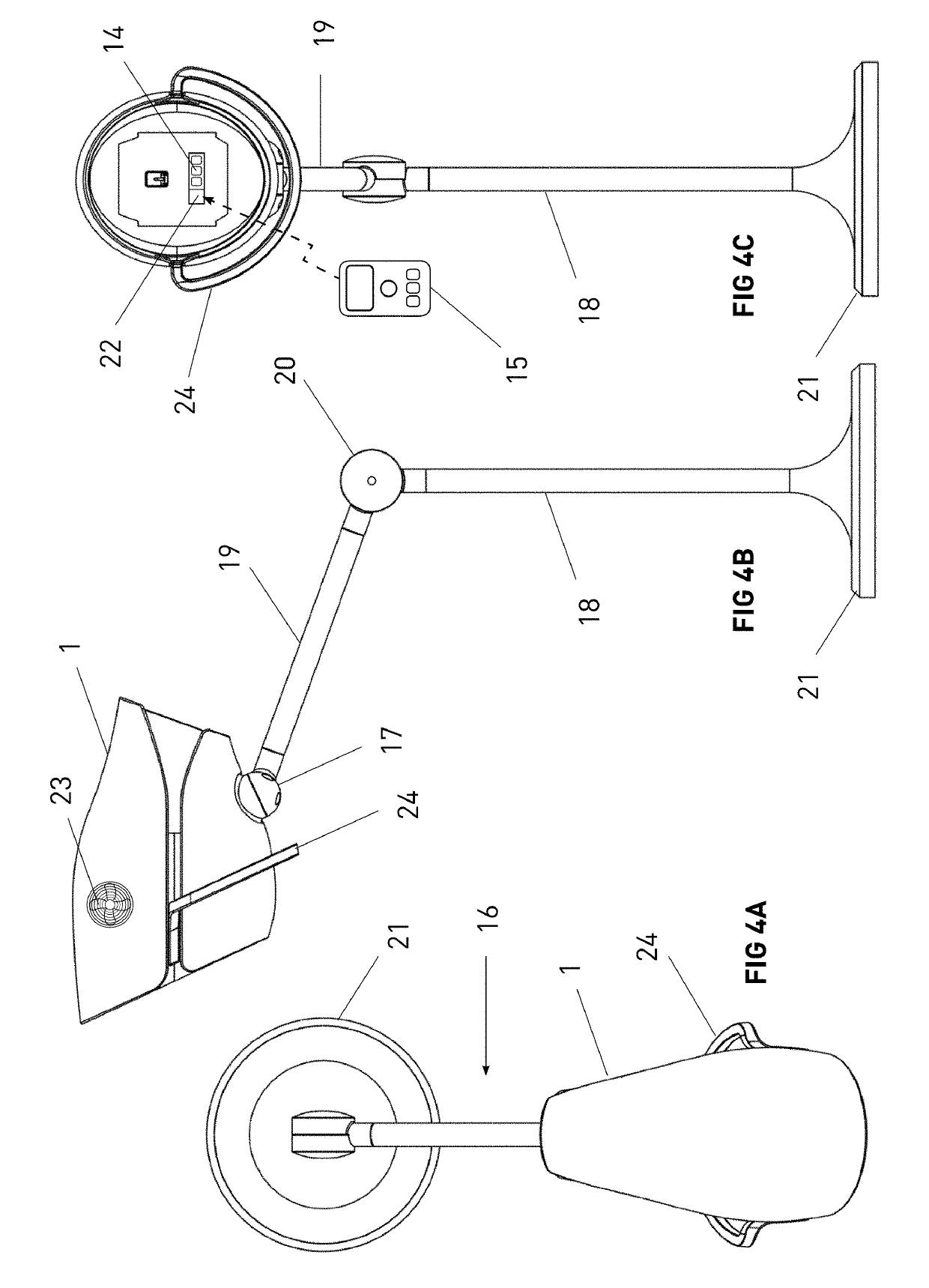
[0023]Referring now to the figures of the drawings in detail and first, particularly, to FIG. 1 thereof, there is seen a helmet 1 which is placed on the head of a user. The helmet 1 is illustrated in the figures as being transparent so as to show the elements contained therein but in practice the helmet is opaque so that light cannot pass through the helmet. The purpose of the helmet is to act as a frame for an electro-optical system disposed inside the helmet and to ensure that the environment inside the helmet is completely dark.

[0024]A concave mirror 2 is placed inside the helmet 1 in a direct line of sight of the user wearing the helmet. The mirror is concave for three reasons: to focus the eyes of the user over a very short distance which is dictated by the size of the helmet, to make the images in the mirror appear larger than they actually are (similar to a makeup mirror), and to make the vision field narrower, so that the user will not see reflections and flashes of light, t...


PUM


Abstract

A skin observation system includes a helmet to be placed over the head of a user, a mirror disposed within the helmet in a direct line of sight of the user wearing the helmet, at least one lighting device disposed within the helmet for illuminating the face of the user, a shield disposed within the helmet for shielding the eyes of the user from light emitted by the at least one lighting device, and a filter disposed within the helmet for filtering components of the light emitted by the at least one lighting device. The lighting device is preferably a plurality of laser diodes and the filter is preferably a UV filter. The mirror preferably has a concave surface facing the user.

Description

BACKGROUND OF THE INVENTIONField of the Invention[0001]The invention relates to a skin observation system which permits a user to observe skin conditions, such as acne, on the user's own face.Description of the Related Art[0002]U.S. Patent Publication No. 20160058157 A1 discloses a headband having a concave mirror for viewing one's own ear. U.S. Patent Publication No. 20080260243 A1 teaches a helmet having a digital camera for recording the color of the hair. U.S. Patent Publication No. 20070002479 A1 shows a device having a flashlight, lenses, filters and a mirror for viewing the skin. Goggles are worn by the user. U.S. Pat. No. 7,532,746 B2 discloses a headset for illuminating the skin with IR and locating blood vessels. U.S. Pat. No. 7,004,599 B2 teaches a hand-held mirror having a polarizer and a light source in a frame covered by a polarizing filter. The two polarizers are out of phase. U.S. Pat. No. 5,760,407 shows a device having a UV light source and a filter for identifying...

Claims


Application Information

Patent Timeline
Patent Type & Authority Applications(United States)
IPC IPC(8): A61B5/00A42B3/04A61B90/50A42B3/28
CPCA61B5/6803A61B5/0079A61B5/441A42B3/044A61B5/7475A61B90/50A42B3/286A42B3/042A61B5/6835A61B5/0077
Inventor SHENFARBER, MOTI
Owner OMM IMPORTS INC
Why Eureka
Try Eureka