Electrooptical probe based on fluid electrooptical materials, and method of using electrooptical probe to detect electric field
An electro-optical material and fluid technology, applied in electrostatic field measurement, components of electrical measuring instruments, measuring electricity, etc., can solve problems such as increasing the cost of electro-optical systems, reducing electro-optical conversion efficiency, and only tens of microns square.
- Summary
- Abstract
- Description
- Claims
- Application Information
AI Technical Summary
Problems solved by technology
Method used
Image
Examples
Embodiment 1
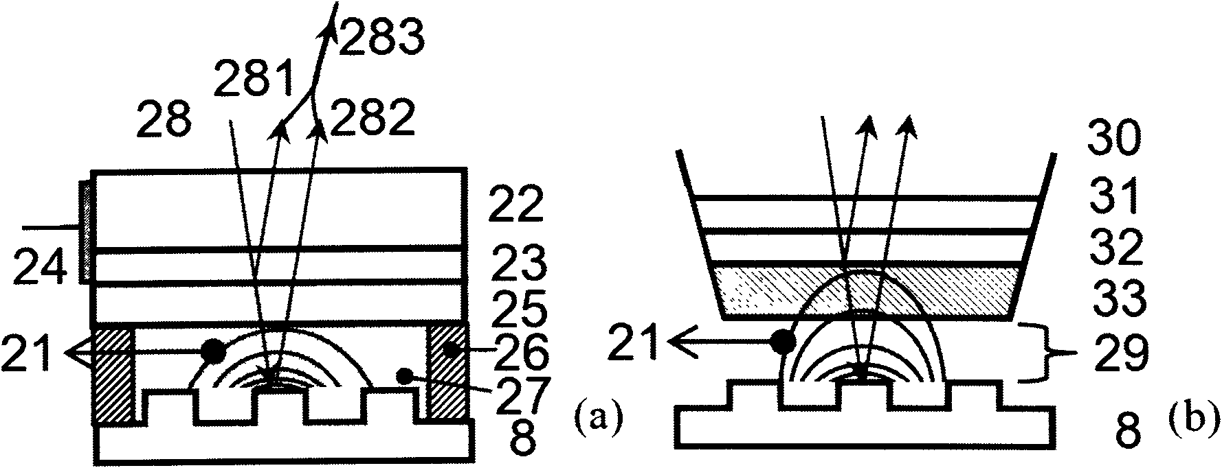
[0066] The structure of the fluid electro-optic probe 7 is as figure 2 As shown in (a), the production steps are as follows:
[0067] 1. Select k9 glass with a thickness of 1mm and optical polishing on the upper and lower surfaces as the material of the transparent substrate 22, and the refractive index for the probe light 1.31 μm is 1.50; use a dicing machine to cut out a square with a size of 2mm*2mm as the fluid electro-optical probe 7 transparent substrate 22;
[0068] 2. On the surface of the transparent substrate 22, use a magnetron sputtering method to sputter an ITO film with a thickness of about 100 nm as the transparent conductive layer 23;
[0069] 3. Wrap the transparent base 22 and the transparent conductive layer 23 layers with tin foil, and expose one side of the side wall of the transparent base 22, evaporate a layer of gold film with a thickness of 0.2 μm on the side wall by thermal evaporation, as the side wall Conductive layer 24, spot welder uses aluminum...
Embodiment 2
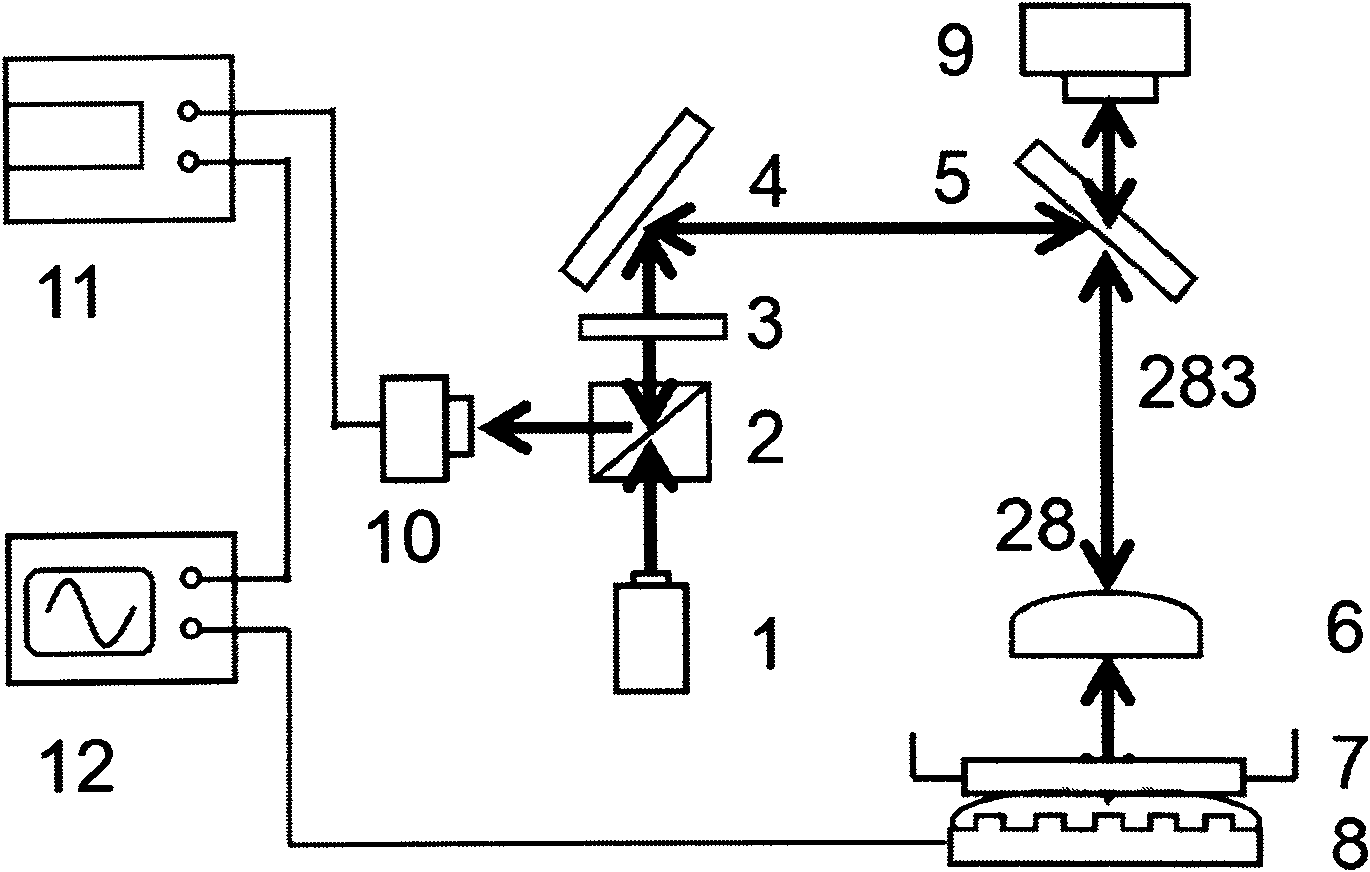
[0074] electro-optic system press figure 1 The connection shown, among them, the implementation of several important parts is as follows:
[0075] Semiconductor laser 1: a 1.31 μm DC semiconductor laser manufactured by Beijing Semiconductor.
[0076] Polarizing beam splitter 2 and λ / 4 wave plate 3: customized by the Laser Institute of Shandong Qufu Normal University according to the experimental parameters.
[0077] Focusing objective lens 6: We use an objective lens with a focal length of 7 mm, a numerical aperture of 0.4, and a magnification of 20 produced by German Zeiss Company.
[0078] Detector 10: GD3561T InGaAs detector produced by Chongqing No. 44 Electronic Technology Group. When the reverse bias voltage is 5V, the responsivity to 1.31μm is 0.85A / W.
[0079] Lock-in amplifier 11: LOCK-IN AMPLIFIER model 5209 of EG&G Company.
[0080] Oscilloscope 12: Rigol's DS1104B multi-channel digital oscilloscope with a measurement bandwidth of 100MHz.
Embodiment 3
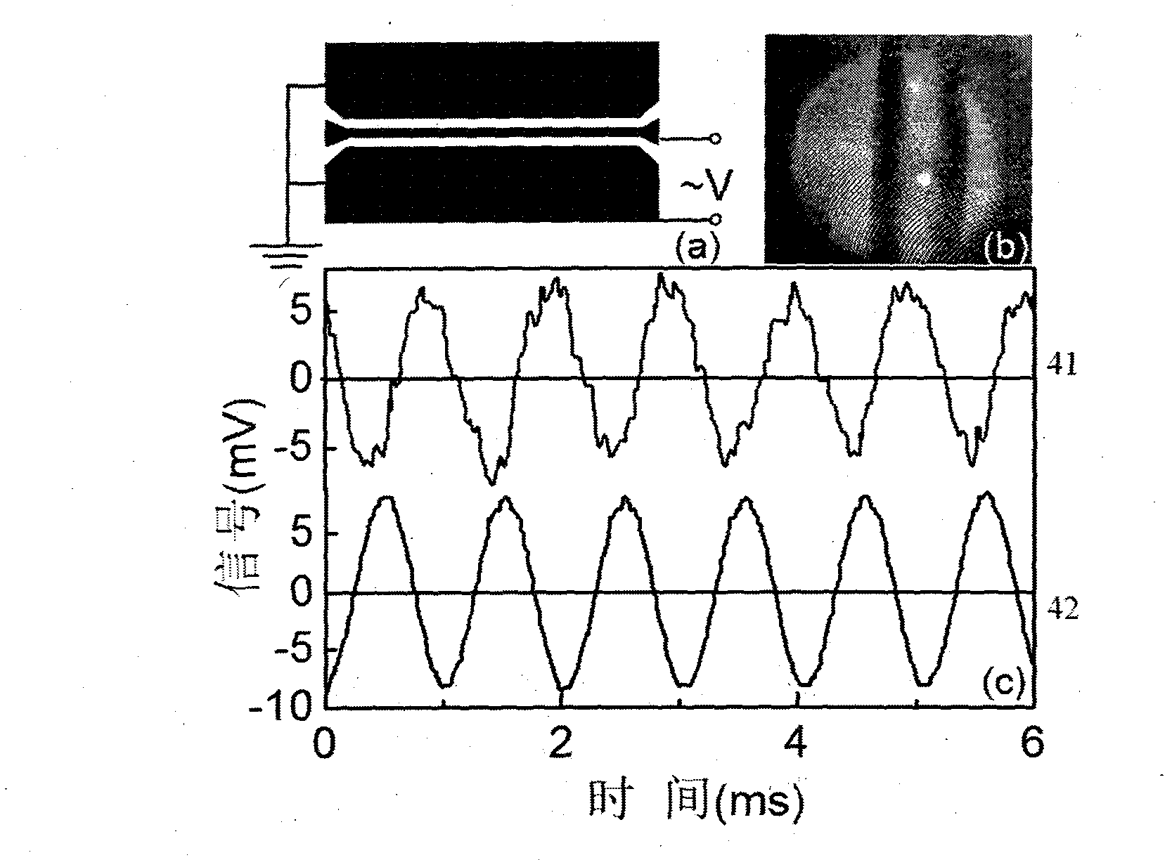
[0081] Example 3: Preparation of coplanar waveguides for electro-optical detection
[0082] A gold film with a thickness of 0.5 μm was prepared by thermal evaporation on K9 glass with a thickness of 2 mm and optical polishing on the upper and lower surfaces, with a size of 2 cm * 3 cm; The coplanar waveguide, whose structure is as image 3 (a) shown.
[0083] The electrical signal is fed into the center wire of the coplanar waveguide, and the electrical signal is provided by a signal generator (EM33151DDS full digital synthesis function signal generator), and the two sides of the center wire of the coplanar waveguide are ground wires. The coplanar waveguide is simulated as an integrated circuit in the experiment as the circuit 8 to be tested. The line width of the center wire is 100 μm, simulating the transmission line on the integrated circuit. The electrical signal on the center wire simulates the electrical signal on an actual integrated circuit.
PUM
 Abstract
Description
Claims
Application Information
 - R&D
- Intellectual Property
- Life Sciences
- Materials
- Tech Scout
- Unparalleled Data Quality
- Higher Quality Content
- 60% Fewer Hallucinations
Browse by: Latest US Patents, China's latest patents, Technical Efficacy Thesaurus, Application Domain, Technology Topic, Popular Technical Reports.
© 2025 PatSnap. All rights reserved.Legal|Privacy policy|Modern Slavery Act Transparency Statement|Sitemap|About US| Contact US: help@patsnap.com


