
Waste slice removing mould

A technology for cleaning waste and molds, applied in metal processing, etc., can solve problems such as low pass rate, tearing and tearing of products, time-consuming, etc., and achieve the effects of improving production efficiency, ensuring quality, and reducing work-related injuries

Inactive Publication Date: 2012-10-03
ZHEJIANG KAISHI LASER TECH CO LTD
View PDF8 Cites 10 Cited by
  • Summary
  • Abstract
  • Description
  • Claims
  • Application Information

AI Technical Summary

Problems solved by technology

[0003] 1. The quality of the product cannot be guaranteed, it is unhygienic, and it is easy to tear off the product and damage it, and the pass rate is low;
[0004] 2. After die-cutting, the edge of the paper will become sharp, and it is easy to hurt the hand when tearing the edge, and small work-related injuries often occur;
[0005] 3. Increase a lot of labor costs
[0006] In short, this method of manual edge tearing not only cannot guarantee the quality of carton products, but also has poor sanitation, frequent work-related injuries, and requires a lot of manpower to operate, which is time-consuming, labor-intensive and cost-intensive. Therefore, it is necessary to improve it.

Method used


Image

  • Waste slice removing mould
  • Waste slice removing mould
  • Waste slice removing mould

Examples


Embodiment Construction

[0018] In order to make the technical means, creative features, goals and effects achieved by the present invention easy to understand, the present invention will be further elaborated below in conjunction with illustrations and specific embodiments.

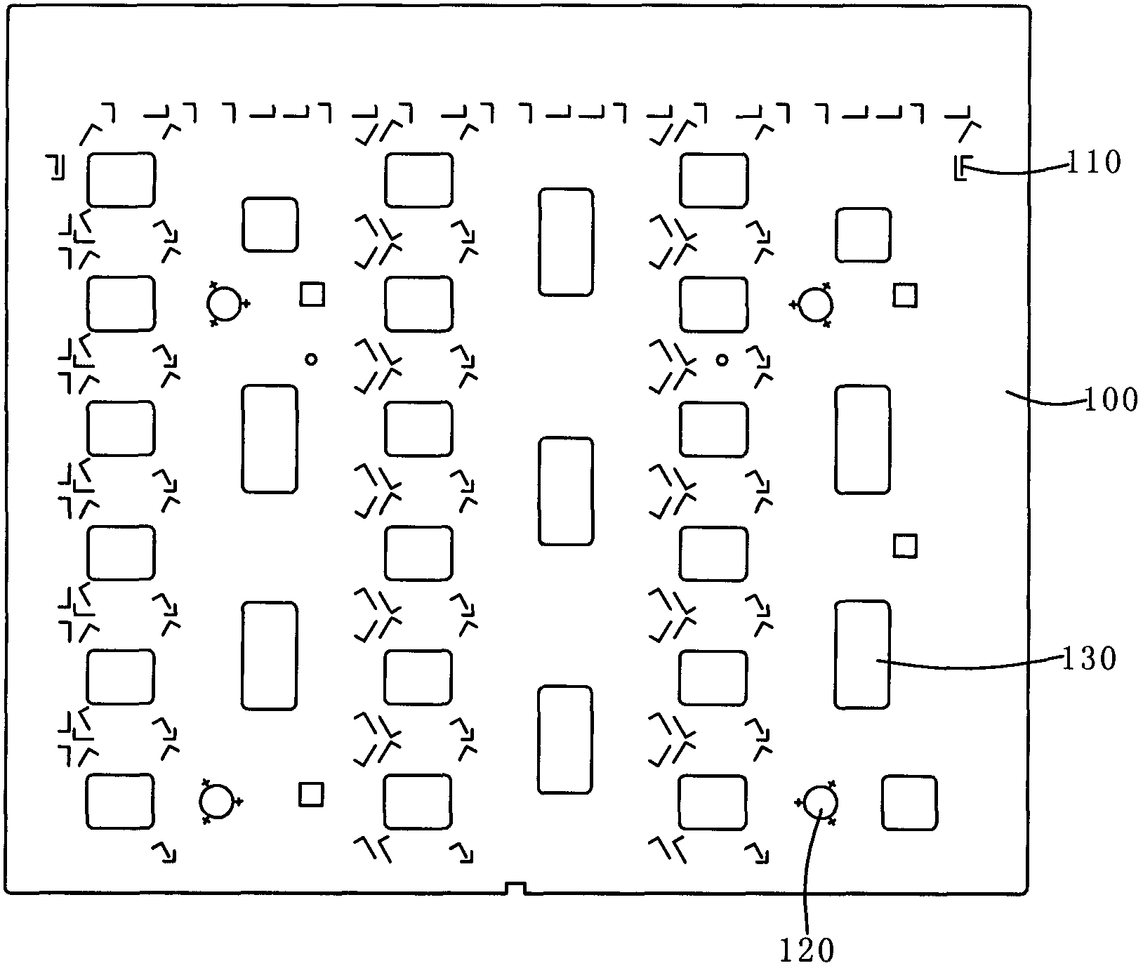
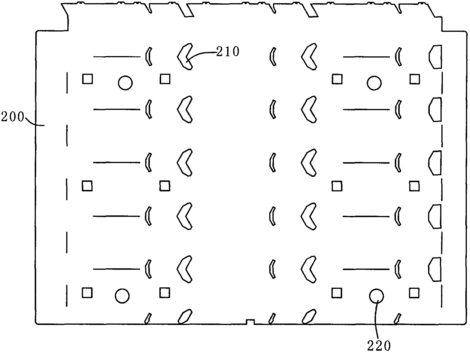
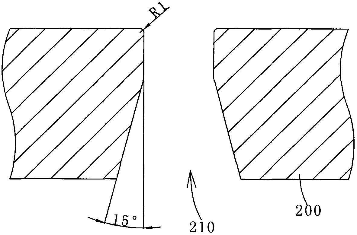
[0019] Such as figure 1 , figure 2 As shown, the stripping sheet mold proposed by the present invention includes an upper template 100 and a lower template 200, the upper template 100 is provided with a stripping knife 110, the lower template 200 has a blanking hole 210, the stripping knife 110 and the The positions of the blanking holes 210 correspond to each other, and the stripping knife 110 presses the finished waste pieces out of the blanking holes 210 to achieve the purpose of stripping; the upper template 100 and the lower template 200 are respectively provided with an upper positioning hole 120 and a lower one. Positioning holes 220, positioning brackets are provided in the positioning holes 120, so that the upper temp...


PUM


Abstract

The invention discloses a waste slice removing mould comprising an upper mould plate, a lower mould plate and a lower mould baffle plate, wherein the upper mould plate is provided with a waste removing knife; the lower mould plate is internally provided with a blanking hole; the waste removing knife and the blanking hole correspond to each other in positions; the waste removing knife extrudes finished waste slices out of the blanking hole to achieve the purpose of waste removal; the upper mould plate and the lower mould plate are respectively provided with positioning holes; positioning supports are arranged in the positioning holes to keep the waste removing knife and the blanking hole to correspond to each other in the positions; a ladder-shaped opening is arranged on the lower end of the blanking hole, a small round chamfer is arranged on the edge of the upper end of the blanking hole, and the width of the upper end is less than that of the lower end so that desquamated waste slices are convenient to discharge; the lower mould baffle plate is positioned on the periphery of the lower mould plate and encloses finished products with wastes to be removed to prevent the finished products from generating displacements in a horizontal direction; and a support frame is connected to the bottom of the lower mould plate to support and fix the lower mould plate. When the waste slice removing mould is in use, the upper mould plate and the lower mould plate are respectively arranged on a support capable of moving up and down, and then a waste removal function is achieved; and in addition, the invention is ensured in product quality, increased in production efficiency and saved in cost.

Description

technical field [0001] The invention relates to a paper product production equipment, in particular to a waste-strip mold for tearing the edge of a cardboard product after die-cutting. Background technique [0002] After the cardboard product is die-cut on the die-cutting machine by a knife die, it is cut into products and waste pieces, and the waste pieces and products are still stuck together. In the existing production process, most of the waste pieces and waste pieces are torn from the edge of the product manually. The method of pulling off, this method has many defects: [0003] 1. The quality of the product cannot be guaranteed, it is unhygienic, and it is easy to tear off the product and damage it, and the pass rate is low; [0004] 2. After die-cutting, the edge of the paper will become sharp, and it is easy to hurt the hand when tearing the edge, and small work-related injuries often occur; [0005] 3. Increase a lot of labor costs. [0006] In short, this method...

Claims


Application Information

Patent Timeline
Patent Type & Authority Applications(China)
IPC IPC(8): B26F1/44B26D7/18
Inventor 陈兴淦
Owner ZHEJIANG KAISHI LASER TECH CO LTD
Learn More