Storage drawer with coiled energy storage pushing trolley

A storage drawer and trolley technology, which is applied in the field of storage drawers, can solve the problems that the storage space needs to be further improved, the convenience needs to be further improved, and the storage drawer has no guiding groove, so as to avoid contact and increase stability , Facilitate the effect of pushing out warehouses

Active Publication Date: 2012-10-03
JIANGSU XUNJIE HARNESS TECH
View PDF9 Cites 5 Cited by
  • Summary
  • Abstract
  • Description
  • Claims
  • Application Information

AI Technical Summary

Problems solved by technology

However, the device still relies on the gravity of heavy objects to slide down, and there is an angle between the storage drawer and the ground, and the storage space still needs to be further improved
[0004] The Chinese patent "A Drawer-Type Boxed Item Storage and Distribution Device with Automatic Push Function" uses a trolley to push, but there is no guide groove under the storage drawer, and there is no handle at the rear, so the convenience of use needs to be further improved

Method used


Image

  • Storage drawer with coiled energy storage pushing trolley
  • Storage drawer with coiled energy storage pushing trolley
  • Storage drawer with coiled energy storage pushing trolley

Examples


Embodiment 1

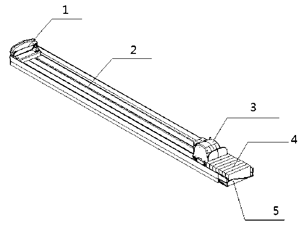
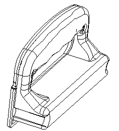
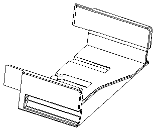
[0025] A storage drawer with a volute energy storage push trolley, comprising a handle 1, a drawer frame 2, a push trolley 3, and a bin outlet 5, wherein the rear end of the drawer frame 2 is provided with a handle 1, and the front end of the drawer frame 2 is provided with a bin outlet Port 5, the push trolley 3 is set on the drawer rack, and boxed items are placed between the push trolley and the exit 5;

[0026] The bottom plate of the drawer frame 2 is provided with three grooves, the three grooves are parallel to each other and parallel to the extension direction of the drawer frame, and the cross section of the middle groove is an inverted "T" shape; The traction line, the power mechanism can drive the winding mechanism to rotate, the winding mechanism is wound with a traction line, the other end of the traction line is fixedly connected to the outlet 5, two sets of rollers are set under the push trolley, and one set of rollers is located at the bottom of the push trolley...

Embodiment 2

[0031] A storage drawer with a volute energy storage push trolley, comprising a handle 1, a drawer frame 2, a push trolley 3, and a bin outlet 5, wherein the rear end of the drawer frame 2 is provided with a handle 1, and the front end of the drawer frame 2 is provided with a bin outlet Port 5, the push trolley 3 is set on the drawer rack, and boxed items are placed between the push trolley and the exit 5;

[0032]The bottom plate of the drawer frame 2 is provided with three grooves, the three grooves are parallel to each other and parallel to the extension direction of the drawer frame, and the cross section of the middle groove is an inverted "T" shape; The traction line, the power mechanism can drive the winding mechanism to rotate, the winding mechanism is wound with a traction line, the other end of the traction line is fixedly connected to the outlet 5, two sets of rollers are set under the push trolley, and one set of rollers is located at the bottom of the push trolley....


PUM


Abstract

The invention discloses a storage drawer with a coiled energy storage pushing trolley, which comprises a handle, a drawer rack, the pushing trolley and an out bin port, wherein three grooves are formed in the bottom plate of the drawer rack, and parallel to one another and to the extending direction of the drawer rack; the cross section of the middle groove is invented T-shaped; a power mechanism, a winding mechanism and a draught line are arranged in the pushing trolley; the power mechanism can drive the winding mechanism to rotate; the draught line is wound around the winding mechanism; the other end of the draught line is fixedly connected to the out bin port; a positioning bulge is arranged at the bottom of the pushing trolley; the cross section of the positioning bulge is invented T-shaped; rollers on the left and the right sides of the pushing trolley are arranged in grooves on two sides of the bottom plate of the drawer rack; the bulge at the bottom of the pushing trolley is arranged in the middle groove of the bottom plate of the drawer rack; after being led out, the draught line on the pushing trolley is also arranged in the middle groove of the bottom plate of the drawer rack; and the handle is arranged on the back of the storage drawer, so as to facilitate grabbing and pushing.

Description

technical field [0001] The invention relates to a storage drawer, in particular to a storage drawer with a scroll energy storage push trolley. Background technique [0002] At present, most of the existing domestic and foreign equipment for automatically distributing items for storage, replenishment, and out of the warehouse are realized by unpowered, slope-type storage tanks. This technical structure is relatively simple, but the main disadvantage is that the slope produces a large inclination angle. The space utilization rate is low, the amount of storage is small, and the replenishment speed is slow, which cannot meet the needs of a large number of replenishment and exit. Especially because of the use of slope storage, without power to push, it depends on the gravity of the items themselves to slide down to achieve the purpose of going out of the warehouse. When the gravity of the items themselves cannot fall down, the phenomenon of stagnation in the storage tank will app...

Claims


Application Information

Patent Timeline
Patent Type & Authority Applications(China)
IPC IPC(8): B65G1/04
Inventor 贡仲林翟东力崔建伟陈志强
Owner JIANGSU XUNJIE HARNESS TECH
Why Eureka
Try Eureka