Phase diversity wavefront sensor

A wavefront sensor and photodetector technology, applied in the field of optical information measurement, can solve the problems of reducing the reliability of wavefront sensor measurement results, measurement result errors, and inconsistency of light intensity, so as to improve the accuracy of wavefront detection and reduce the impact , the effect of high utilization rate of light energy

Inactive Publication Date: 2014-08-20
INST OF OPTICS & ELECTRONICS - CHINESE ACAD OF SCI
View PDF2 Cites 0 Cited by
  • Summary
  • Abstract
  • Description
  • Claims
  • Application Information

AI Technical Summary

Problems solved by technology

[0003] Typical wavefront sensor structure based on phase difference method, see "Wavefront detection technology based on phase difference method" [Li Qiang, Shen Mangzuo. [J]. Optoelectronic Engineering, 2006, 33(11)], mainly imaging system , a beam splitter and two array photodetectors, the beam splitter is located between the imaging system and the focal plane of the imaging system, and the two array photodetectors are respectively placed at the focal plane of the imaging system of the original optical path and the defocused plane of the optical path The position is used to detect two images on the focal plane and the defocused plane at the same time. Its disadvantage is that the aberration of the beam splitter itself will bring errors to the measurement results, and the beam splitting performance of the beam splitter will bring the light of the two paths Strong inconsistency will also have a certain impact on the measurement results
However, in some wavefront measurements, especially those involving high-precision wavefront measurements, the existence of these error factors greatly reduces the reliability of the wavefront sensor measurement results based on the phase difference method and limits its application.

Method used


Image

  • Phase diversity wavefront sensor
  • Phase diversity wavefront sensor
  • Phase diversity wavefront sensor

Examples


Embodiment Construction

[0018] In order to make the object, technical solution and advantages of the present invention clearer, the present invention will be described in further detail below in conjunction with specific embodiments and with reference to the accompanying drawings.

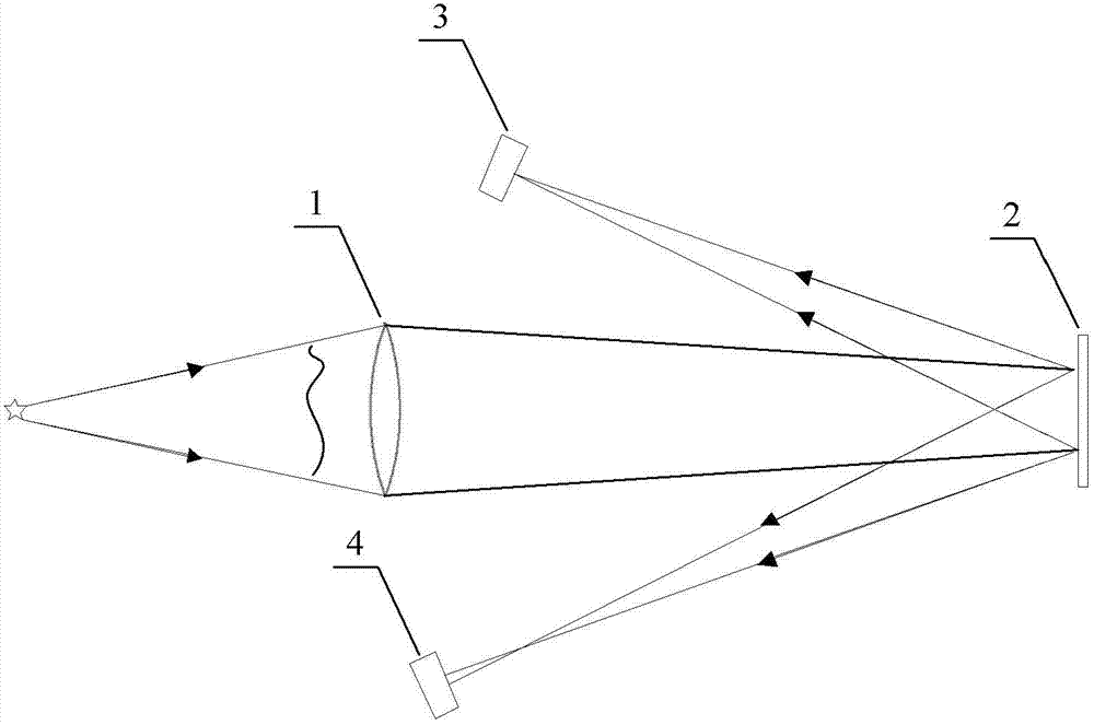
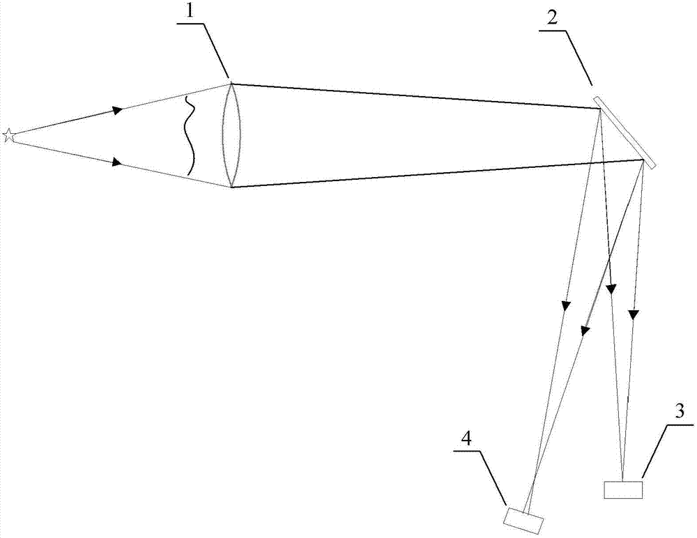
[0019] Such as figure 1 As shown, the phase difference method wavefront sensor is composed of an imaging unit 1, a digital micromirror device 2, a first array photodetector 3 and a second array photodetector 4, wherein: the digital micromirror device 2 is located in the imaging unit 1 Between it and its focal plane position, after the light beam emitted by the target passes through the imaging unit 1, the digital micromirror device 2 deflects and modulates the light beam, so that the light beam is reflected in two directions respectively, and the target image is formed in the two reflection directions respectively; An array type photodetector 3 and a second array type photodetector 4 are respectively positioned on two ref...


PUM


Abstract

The invention relates to a phase diversity wavefront sensor, comprising an imaging unit, a digital micro-mirror device, first and second array type photoelectric detectors; the digital micro-mirror device is located between the imaging unit and a focus plane position; after the light beams sent by the target pass through the imaging unit, the digital micro-mirror device modulates the deflection of the light beams so that the light beams are reflected towards two directions respectively and formed with target images respectively on two reflecting directions; the first and second array type photoelectric detectors are located on two reflecting directions of the digital micro-mirror appliance respectively, and the first array type photoelectric detector is located on an out-of-focus surface of the imaging unit to detect an out-of-focus image after imaging the target by the imaging unit; if the imaging unit is a space invariant linear system, the target function is determined according to the maximum likelihood estimation; the solution for minimizing the target function E is searched by adopting the optimization algorithm, and thus the wavefront phase distribution is solved.

Description

technical field [0001] The invention belongs to the technical field of optical information measurement, and relates to a device for measuring the wavefront aberration of an incident light beam, in particular to a phase difference method wavefront sensor. Background technique [0002] The wavefront sensor based on the phase difference method mainly uses two images collected at the same time on the focal plane and the defocused plane of known size to restore the phase distribution of the incident light wave, and it can also restore the target. Compared with the Hartmann wavefront sensor and shear interferometer, the wavefront sensor based on the phase difference method has a simple optical path structure, is easy to implement, and can detect both point targets and extended targets; compared with traditional single-frame far-field sensors such as GS The phase recovery algorithm of the image is different. The phase difference method uses the far-field spot distribution images of...

Claims


Application Information

Patent Timeline
Patent Type & Authority Patents(China)
IPC IPC(8): G01J9/04
Inventor 王帅杨平许冰
Owner INST OF OPTICS & ELECTRONICS - CHINESE ACAD OF SCI
Why Eureka
Try Eureka