Automobile tail gas pipe temperature difference power generation device

A technology of automobile exhaust and thermoelectric power generation, which is applied to exhaust devices, mufflers, generators/motors, etc., can solve the problems of reducing manufacturing costs, increasing the weight of devices, affecting automobile exhaust emissions, etc., and achieving lightweight and easy installation of products. and disassembly, energy saving effect

Active Publication Date: 2012-10-03
HUANENG CLEAN ENERGY RES INST
View PDF8 Cites 11 Cited by
  • Summary
  • Abstract
  • Description
  • Claims
  • Application Information

AI Technical Summary

Problems solved by technology

This technical solution needs to modify the exhaust pipe, which is difficult to modify. In addition, for the exhaust pipes of different brands of automobiles with different exhaust structures, the connected thermoelectric power generation device may have hidden dangers affecting the exhaust emissions of automobiles.
[0006] Chinese patent CN200997576Y discloses a technical solution, which uses arc-shaped thermoelectric sheets to be directly fixed on the outer surface of the exhaust pipe, avoiding changes to the structure of the automobile exhaust pipe. However, high

Method used


Image

  • Automobile tail gas pipe temperature difference power generation device
  • Automobile tail gas pipe temperature difference power generation device
  • Automobile tail gas pipe temperature difference power generation device

Examples


Embodiment Construction

[0035] The embodiments of the present invention will be described in detail below with reference to the accompanying drawings, but the present invention can be implemented in many different ways defined and covered by the claims.

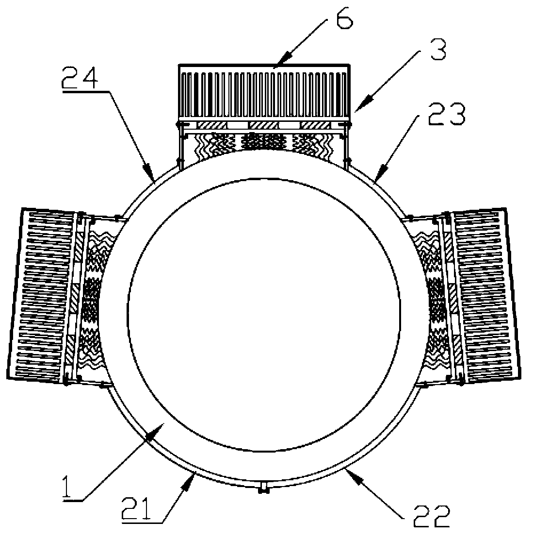
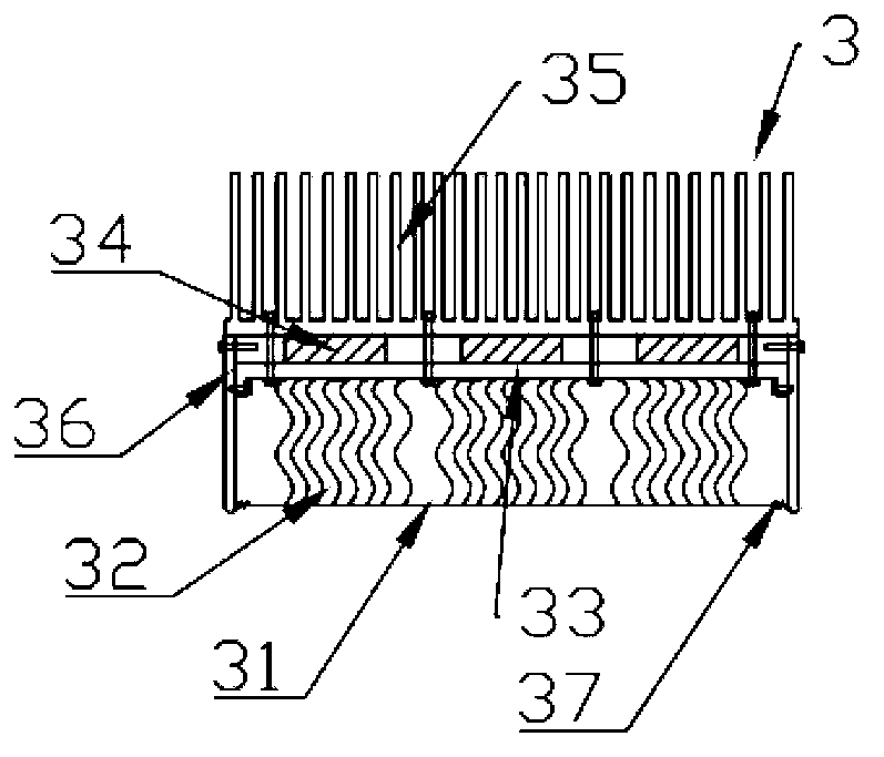
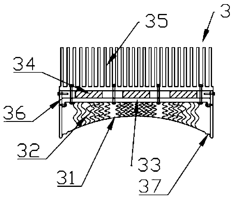
[0036] Figure 1 to Figure 4 The structure of an embodiment of the automobile exhaust temperature difference power generation device according to the present invention is shown. Such as Figure 1 to Figure 4 As shown, the automobile exhaust pipe thermoelectric power generation device of the present invention includes: at least two thermoelectric power generation modules 3 arranged on the outer periphery of the automobile exhaust pipe 1 along the circumferential direction of the automobile exhaust pipe, and each thermoelectric power generation module 3 includes a rigid substrate 33 , heat dissipation substrate 35, several thermoelectric chips 34 sandwiched between the rigid substrate 33 and the heat dissipation substrate 35, two heat shields 36 arra...


PUM


Abstract

The invention discloses an automobile tail gas pipe temperature difference power generation device, which comprises at least two temperature difference power generation modules, a first connecting piece and a hoop mechanism, wherein the at least two temperature difference power generation modules are arranged on the periphery of an automobile tail gas pipe along the peripheral direction of the automobile tail gas pipe; each temperature difference power generation module comprises a rigid substrate, a radiating substrate, a plurality of thermoelectric sheets arranged between the rigid substrate and the radiating substrate, two insulation boards which are arranged on two sides (along the peripheral direction of the automobile tail gas pipe) of the rigid substrate, and a flexible heat-conducting base for transferring heat to the rigid substrate from the automobile tail pipe; the first connecting piece is connected between the insulation boards of adjacent two temperature difference power generation modules along the peripheral direction of the automobile tail gas pipe; and the hoop mechanism comprises a second connecting piece and a third connecting piece which are respectively connected with the insulation boards of adjacent two temperature difference power generation modules and are on the periphery of the automobile tail gas pipe and along opposite directions, and screwing bolts connected with the second connecting piece and the third connecting piece. The temperature difference power generation device is portable and easy to mount and detach, and power generation power can be freely matched, so that the use of the automobile exhaust power generation device is facilitated.

Description

technical field [0001] The invention relates to an automobile exhaust pipe thermoelectric power generation device. Background technique [0002] The automobile industry is one of the pillar industries of my country's national economy. With the development of my country's automobile industry, the energy-saving issues of vehicles are getting more and more attention. However, more than 60% of the energy in the fuel consumed by the internal combustion engine has not been effectively utilized, and most of it is discharged into the atmosphere in the form of waste heat from automobile exhaust, causing huge economic losses and energy waste. According to measurements, the exhaust temperature of automobiles during driving can reach above 600°C. If this part of heat is recycled reasonably, the fuel consumption of automobiles can be greatly saved, and energy saving can be achieved at the same time, which has good social and economic benefits. [0003] The use of semiconductor thermoel...

Claims


Application Information

Patent Timeline
IPC IPC(8): H02N11/00F01N5/02
CPCY02T10/16Y02T10/12
Inventor 金安君许世森彭文博刘大为李启明
Owner HUANENG CLEAN ENERGY RES INST
Why Eureka
Try Eureka