Straw incinerator

An incinerator and straw technology, applied in the field of straw incinerators, can solve the problems of hindering the popularization and application of straw incineration, low power generation efficiency, low calorific value of straw, etc. The effect of high incineration efficiency

Active Publication Date: 2015-06-10
浙江西塘实业有限公司
View PDF7 Cites 0 Cited by
  • Summary
  • Abstract
  • Description
  • Claims
  • Application Information

AI Technical Summary

Problems solved by technology

At present, straw incineration plants in various places are often in a state of half-work and half-stop production, which is closely related to the defects of straw incineration itself: on the one hand, straw is fluffy in texture. Before the grass is incinerated, another processing program is set up to process it, or it is crushed and compressed into a pinecone shape for incineration, or it is directly bundled and then cut section by section to be sent to the incinerator, all of which invisibly aggravate the On the other hand, the calorific value of straw is low, and the power generation efficiency per unit volume is extremely low. It is obviously unrealistic to build a special straw incinerator for purely burning straw. Compared with the same weight of coal, the straw occupies a huge stacking site. Just because of the seasonal output of straw and the difficulty of wide-scale purchase, it often makes it difficult for professional straw incinerators to burn continuously; At present, various improvements have been made in response to the above situation, which has brought great obstacles to the promotion and application of straw incineration.

Method used


Image

  • Straw incinerator
  • Straw incinerator
  • Straw incinerator

Examples


Embodiment Construction

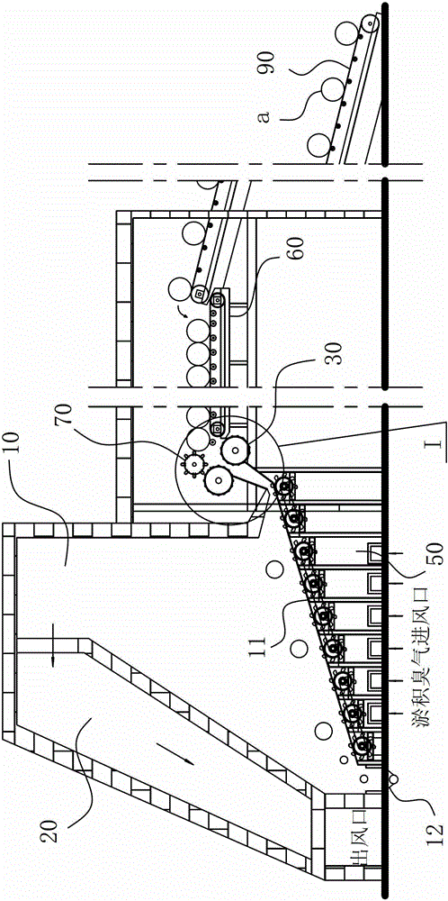
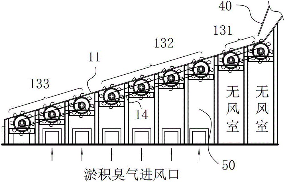
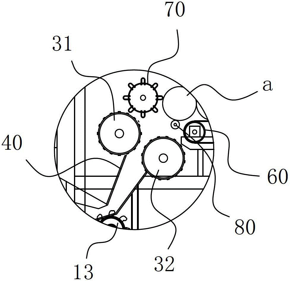
[0010] A straw incinerator comprises a combustion chamber 10 and a flue 20 for extracting heat energy in the combustion chamber 10, the combustion chamber 10 is provided with a delivery platform 11 for burning and transporting molded straw; the straw incinerator also Comprise rigid extruding unit 30, rigid extruding unit 30 comprises the two extruding parts that mutually constitute extruding fit, and described at least one extruding part is pressure roller; The extruding gap of described rigid extruding unit 30 and straw The thickness to be extruded is consistent, and its outlet conveying path points to the table where the feeding end of the conveying platform 11 is located, actually as Figure 1-4 shown.

[0011] As a further preferred solution of the present invention: the outlet end of the flue 20 is connected to the air inlet chamber of the external combustion furnace, and the flue 20 communicates with the combustion chamber 10 through the vent at the top of the combustion...


PUM


Abstract

The invention belongs to the field of waste incineration, and in particular relates to a straw incinerator. The straw incinerator comprises a combustion chamber, a flue for inducing heat energy in the combustion chamber out, and rigid extrusion unit, wherein a conveying platform for incinerating and conveying formed straws is arranged in the combustion chamber, the rigid extrusion unit comprises two extrusion parts which are in extrusion fit with each other, at least one extrusion part is a compression roller, an extrusion clearance of the rigid extrusion unit is matched with the thickness of the straws to be extruded and formed, and an outlet conveying path of the rigid extrusion unit is directed to a table board on which the feed end of the conveying platform is arranged. According to the invention, by virtue of the conveying platform, the formed straws can be conveyed and incinerated continuously; and by virtue of the rigid extrusion unit at the feed end of the conveying platform, the straws to be incinerated can be extruded to form synchronously, and furthermore, the formed volume and incineration efficiency of the straws better satisfy practical requirements; and the straw incinerator has high integral operation reliability and high incineration efficiency, is low in application cost, and can be used for effectively realizing the seasonal efficient incineration of the straws.

Description

technical field [0001] The invention belongs to the field of garbage incineration, and in particular relates to a straw incinerator. Background technique [0002] Straw is the general term for the stems and leaves (ears) of mature crops, and usually refers to the remaining parts of wheat, rice, corn, potatoes, oilseeds, cotton, sugar cane and other crops after harvesting seeds. With the gradual advancement of social science and technology, the country's quality supervision of the air environment has become increasingly strict, and the past self-burning of straw has been unable to be recognized by the country. Most of the existing treatment methods for straw are purchased by the incineration plant and sent to a special straw incinerator for systematic incineration. The various gases and smoke produced by the incineration are also purified by the incineration plant itself. Conditions to be purified before being discharged into the outside air. At present, straw incineration ...

Claims


Application Information

Patent Timeline
Patent Type & Authority Patents(China)
IPC IPC(8): F23G5/033F23G5/44
Inventor 李登平
Owner 浙江西塘实业有限公司
Why Eureka
Try Eureka