Eureka AIR delivers breakthrough ideas for toughest innovation challenges, trusted by R&D personnel around the world.

Electrically-assisted magnetic core power machine

A power machine and magnetic core technology, applied in the direction of generators/motors, electrical components, etc., can solve the problems of unbalanced driving speed, insufficient driving force, and instability, and achieve the effect of balanced and stable rotation, controllable speed, and sufficient power.

Inactive Publication Date: 2012-10-10
杨建国
View PDF1 Cites 0 Cited by
  • Summary
  • Abstract
  • Description
  • Claims
  • Application Information

AI Technical Summary

Problems solved by technology

However, due to reasons such as the way and structure of the existing magnetic power machine, its driving speed is unbalanced and unstable, resulting in insufficient driving force, and it has basically failed to truly realize industrial utilization.

Method used


Image

  • Electrically-assisted magnetic core power machine
  • Electrically-assisted magnetic core power machine
  • Electrically-assisted magnetic core power machine

Examples


Embodiment Construction

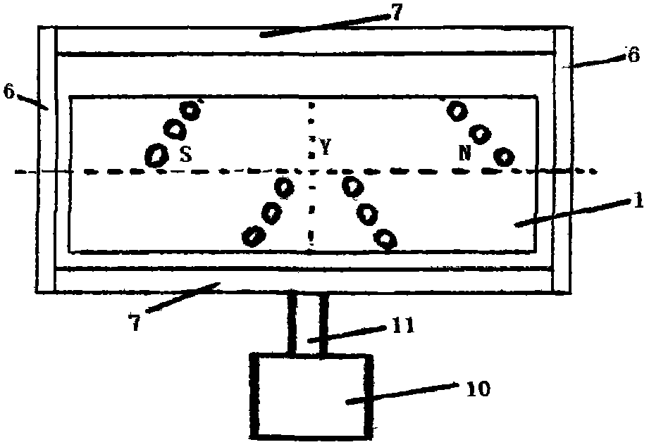
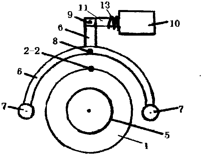
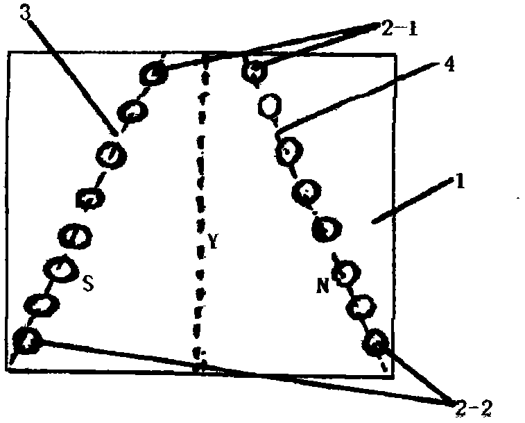
[0009] The present invention will be further described through embodiment now in conjunction with accompanying drawing. Such as Figure 1-6 As shown, a set of magnet groups composed of several magnetic blocks 2 is provided on the peripheral wall of the rotor 1, and the magnet group is formed by a plurality of magnet blocks 2 in two rows along the circumferential direction of the rotor 1 and distributed at equal intervals on the radial direction line on the peripheral surface of the rotor 1. On the y side, along the circumferential direction of the rotor 1, it is formed on the oblique lines 3 and 4 of the two Swiss directions of the rotor 1. The slopes of the two oblique lines 3 and 4 are equal and symmetrical to the radial direction line y. The two magnetic blocks 2 on the opposite left and right sides on the same axial direction line on the peripheral wall of the rotor 1 have opposite polarities (respectively N and S poles) and form a pair with each other. The magnetic bloc...


PUM


Abstract

The invention discloses an electrically-assisted magnetic core power machine which is balanced and stable in rotation and sufficient in power. The electrically-assisted magnetic core power machine comprises a support, a stator and a rotor magnet. An electromagnet drives a stator magnet to away from a rotor magnetic resistance, the rotor magnet consists of a magnet set which is formed in a way that a plurality of magnets in two rows along the periphery of the rotor are distributed at equal intervals on two inclined lines on two sides of a radial direction line on the peripheral surface of the rotor, and each two magnets on the same axial direction line are in a pair and opposite in polarity. The electrically-assisted magnetic core power machine is a device which uses a proximity switch for triggering the electromagnet to drive the stator magnet to rotate away from the rotor magnetic resistance.

Description

Technical field: [0001] The invention relates to a power device, in particular to an electric-assisted magnetic core power machine. Background technique: [0002] As a power device, the magnetic motor has the advantages of low noise, low energy consumption, and sufficient power, etc. instead of electric motors or internal combustion engines. However, due to reasons such as the mode and structure of the existing magnetic power machine, its driving speed is unbalanced and unstable, resulting in insufficient driving force, and basically fails to truly realize industrial utilization. Invention content: [0003] This invention is invented on the basis of my previous authorized patent (201120045462.7), adding an electric starting device, the electric assisted magnetic core power machine has a balanced and stable rotation speed, more powerful power, simple structure and controllable speed. [0004] The technical scheme of the present invention includes a bracket, a stator magnet...

Claims


Application Information

Patent Timeline
IPC IPC(8): H02N11/00
Inventor 杨建国
Owner 杨建国
Why Eureka
Eureka Blog
Learn More